42 coolant temperature sensor wiring diagram
1993 1995 Iat And Ect Sensor Wiring Diagram Jeep 4 0l. Toyota 4runner Engine Coolant Temperature Receiver Gauge Malfunction Meter System Service Manual. P0117 P0118. Hyundai Accent Engine Coolant Temperature Sensor Ects Schematic Diagrams Control System Fuel. Joined Aug 15, 2009. ·. 5,819 Posts. #12 · Sep 3, 2011. cose 6 is for ect (engine coolant temp sensor) its the one on the side of the head under the dizzy with two wire plug on it....check the wire for a brake,bad connection..all so make sure the wire is in the right spot at the ecu plugs,it should be at a13 on the obd-1 side of the ecu plug ...
How to change thermostat and coolant temperature sensor P20 ... ... Amazon.com ANGLEWIDE Engine Coolant Temperature Sensor 20 ...

Coolant temperature sensor wiring diagram
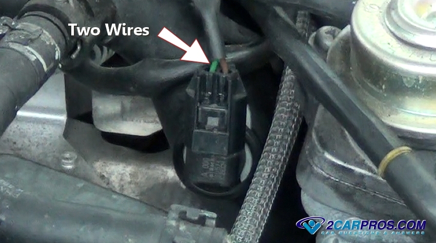
... Diagram 97 Grand Prix Coolant Temperature Sensor Wiring Diagram 2003 Polaris Sportsman 500 Fuse Box 1995 Dodge Ram Pcm Wiring Diagram 1949 Ford Custom ... The coolant temp sender for the gauge has one wire, dark green. That one is in the left cylinder head between the first two spark plus. The coolant temp sensor for the PCM has two wires and is located near the thermostat. Assuming this is not a diesel engine. On 1st gen auto 12v's there is what you are referring to. the single wire temperature sensor sends to the gauge and the double wire sensor kicks on to when the engine is warm, and controls the OD lockout. it is about 4 -5" to the rear of the engine from the intake air temperature sensor. on first gens it has 2 wires one white one blue.
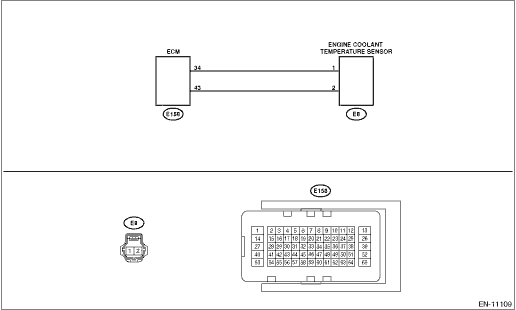
Coolant temperature sensor wiring diagram. I Was Told That Was My Problem. Asked by Bill Cook2 ·. 3 ANSWERS. 1 IMAGE. 2006. HYUNDAI ELANTRA. Coolant Temperature ... Wiring diagram Motronic engine control module (ECM), knock sensors, intake air temperature (IAT) sensor, engine coolant temperature (ECT) sensor ws = white sw = black ro = red br = brown gn = green bl = blue gr = grey ge = yellow li = violet No. 72/6 EuroVan G2 - Engine Coolant Temperature (ECT) Sensor G61 - Knock Sensor (KS) 1 COOLANT TEMPERATURE SENSOR WIRING DIAGRAM. Watch later. Share. Copy link. Info. Shopping. Tap to unmute. If playback doesn't begin shortly, ... Coolant Temperature Sensor Wiring Diagram Print the cabling diagram off and use highlighters to trace the routine. When you make use of your finger or stick to the circuit together with your eyes, it is easy to mistrace the circuit. 1 trick that I use is to print exactly the same wiring diagram off twice.
The wiring I sent you already will help with the coolant temp sensor . The fan is also controlled bu the ECM and that should also be in the wiring I sent ! Ask Your Own Medium and Heavy Trucks Question If you notice coolant in front of the motor, it may be coming from the engine coolant temperature sensor ’ s location. Coolant Temperature Sensor Wiring Diagram - wiring diagram is a simplified enjoyable pictorial representation of an electrical circuit. It shows the components of the circuit as simplified shapes, and the gift and signal friends between the devices. A wiring diagram usually gives counsel virtually the relative outlook and conformity of ... Sensor – The water temperature sensor signal as described in the wiring diagrams below ... fan and are not an indicator of engine coolant temperature.
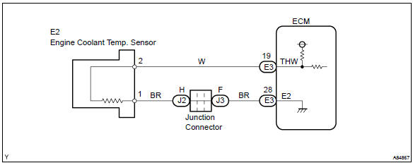
Engine Coolant Temperature Sensor Wiring Diagram - wiring diagram is a simplified normal pictorial representation of an electrical circuit. It shows the components of the circuit as simplified shapes, and the capability and signal contacts surrounded by the devices. A wiring diagram usually gives guidance practically the relative position and ... source: cobalt coolant temperature sensor diagram. cobalt the 2.2l and 2.4l coolant temperature sensor location is located on thermostat housing.the 2.0l engine coolant temperature sensor location right front passengers side corner of the cylinder head near the valve cover. posted on aug 20, 2010 anybody have a diagram for which wires go to where for the coolant temp sensor on the bottom of the coolant neck? the wires all broke on mine, and the car is stuck in cold mode, i want to re wire it with some better connecters. i know there is a green/black wire and a green/yellow wire. thanks for the help The coolant Temp Sensor has two units in one (G62 & G2) G62 is connected to the ECU via Brown/Green wire (at T121/104 at ECU) and Blue/Brown wire (at T121/112 at ECU). G2 is connected to the Temp Gauge in the Cluster via a Lilac wire. The other wire, Brown/White, goes to a common "splice" labeled as #269.
Engine Coolant Temperature Sensor Ect Symptoms Of A Bad Ect Sensor Youtube
Coolant Temperature Sensor Wiring Help - Audi Forums, size: 800 x 600 px, source: www.audi-forums.com. 03-'05) Coolant Temp Gauge Dying - Video Inside - Subaru Forester, size: 800 x 600 px, source: www.subaruforester.org. How To Install Replace Engine Coolant Temperature Sensor 5.7L, size: 800 x 600 px, source: i.ytimg.com.
Microsquirt Introduction
Wiring Diagrams And Free Manual Ebooks 2007 Lexus Es350 ... Coolant Temperature Sensor Location Where Is The Coolant

Temperature Gauge Wiring Diagram Electrical Diagram Gauges Electrical Circuit Diagram
The coolant temp sensor for the pcm has two wires and is located near the thermostat. Get the engine surface temperature using an infrared thermometer or suitable cooking thermometer. Find your coolant temperature sensor wiring diagram here for coolant temperature sensor wiring diagram and you can print out. Search for coolant temperature ...

Alh Coolant Temperature Sensor Wiring Tdiclub Forums
Nov 18, 2020 - Ls1 Engine Wiring Diagram and Ls Engine Controls ... Wiring Diagram For Code 33 - MAP Sensor Circuit (Signal Voltage High - Low Vacuum).
L300 4d56 2007 Voltage To Engine Coolant Temp Sensor Fluctuates Rapidly Mitsubishi Forums
Coolant temp sensor is an easy fix. Its on the front of the engine by the thermostat. If your gauge isn't working, pull the wire from the sensor and ground it. If the needle jumps, your gauge is good. The sensor is less than $15.00 When you replace it don't put sealant on the first few threads. They need to be clean for a good ground.

Coolant Temp Sensor Wiring Confirmation Needed Nasioc
automatic fan/coolant temperature sensor wiring diagram ECU pin out suzuki beleno part 2 urdu
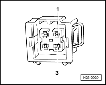
1
Prius hybrid 2010 Wiring Diagrams Request ... Peugeot 508 coolant temperature sensor wiring diagram to ecu ... Q8 Quattro V6 Hybrid wiring diagrams

Engine Coolant Temperature Sensor Youtube
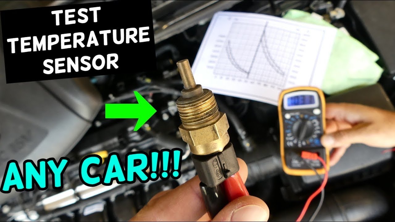
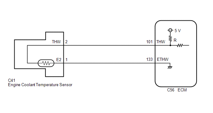
Learn the electronics of the engine coolant temperature sensor. See how it all ties together in the ECM (engine control module).

Npn Vehicles Engine Coolant Sensors
Joined Feb 21, 2008. ·. 7,482 Posts. #10 · Aug 8, 2010. Xanderbilt said: Been away from here and my Vette for about a year now while battling a disease. I located the temperature sensor and where it needs to hook up. The user manual says to drain the coolant before removing the sensor from the head.
Hyundai Accent Engine Coolant Temperature Sensor Ects Schematic Diagrams Engine Control System Engine Control Fuel System
For that sensor all of the information I have doesn't show the ECT sensor you have being used on your engine in your vehicle, it shows only the cylinder head temperature sensor being used for the coolant temp input and fan control inputs to the ECM. Normally the newer Fords only use one or the other and not both types of sensor.

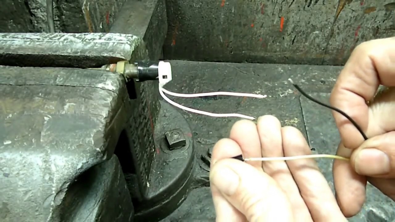
How To Test Coolant Temp Sensor Connector Tdiclub Forums
Please see more wiring amber you will see it in the gallery below. Thank you for visiting our website to locate Engine Coolant Diagram. . Hopefully we provide this is helpful for you. engine coolant temperature sensor wiring diagram collection water pump diagram - water pump fits nissan primera p10 2 0d 91 to well known water pump ...

3 Pin Coolant Sensor For 2gr Mr2 Owners Club Forum
the 3 wire sensor can be found on S10 with the later body style also typically less than a dollar at the yard I had bought 4 or 5 after doing this mod on shbox you can see the resistance chart to test the sensor resistance. the resistance read on the sensor will be close to outside ambient air temperature if you go this route

Dohc Engine Swap Finally Modular High Performance Crownvic Net
Intake Air Temperature and Pressure Sensor - 53032649AA 2005 Coolant Temperature Sensor - 5114413AA MAP/IAT Sensor - 5139278AA Intake Air Heater Relays - 472737AA 4.2 GROUNDING THE VEHICLE A perfectly and beautifully wired automobile will nevertheless have problems if everything is not properly grounded. Don't go to the effort of ...

Engine Oil Temperature Sensor Its Location Symptoms Wiring Diagram Working Function
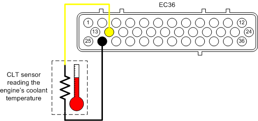
Coolant Temperature Sensor The coolant temperature sensor is a negative temperature coefficient resistor (NTC). The resistance signal it produces is used by the control unit to determine: The amount of cold start and warm-up enrichment Ignition timing and idle stabilization during warm-up
9 2 Coolant Temperature
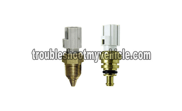
The engine coolant temperature (ECT) sensor is a resistor-based sensor, which measures the temperature of the engine's coolant.. It sends the reading to the car computer (ECU), which adjusts the amount of fuel injection into the combustion chamber. The ECT sensor comes in different wiring diagrams and colors depending upon the car.

Gsic Global Service Information Center
21 Sept 2015 ... Kubota tractor wiring diagrams just another data within coolant temperature sensor. The wires all broke on mine and the car is stuck in cold ...
Hyundai Elantra Engine Coolant Temperature Sensor Ects Schematic Diagrams Engine Control System Fuel System Hyundai Elantra Md 2010 2015 Service Manual
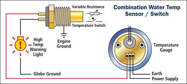
Bad coolant temp sensor or ground? help asap. Which coolant temp sensor sends to the gauge?. 4 wire wiring diagram temp sensor diagram base website temp sensor. 035919501 coolant temperature sensor /water temperature sensor for vw,au di,volvo for sale. Oil temp sensor wire diagram. Bmw z3 coolant temperature sensor testing and replacement.

Ray List Catec 4826 On Car Input Sensors And Actuators On Vehicle
... Wiring Order , Delco Alternator Wiring , Amp Wiring Kit Best Buy , 2004 Chevy Trailblazer Pcm Wiring Diagram , Rv Converter Wiring Diagram , 8n Ford ...
Ect Sensor What It Is How It Works And More
Home » Sensors & fittings » Universal coolant or oil temperature sensor M12x1.5mm ... Please note, this sensor does not share the ...

Need To Wire Coolant Temp Sensor Honda D Series Forum
An engine coolant temperature sensor or ECT measures the temperature of the liquid coolant. A typical engine cooling temperature sensor is a Negative Temperature Coefficient (NTC) thermistor, which means its electrical resistance decreases when the temperature increases. The tip of the ECT sensor protrudes into one of the cooling system ...
Engine Coolant Temperature Sensor Connector Replacement Updated Youtube
Lt1 coolant temp sensor wiring diagram 4th gen f body tech articles 67 camaro coil i have a 94 z28 with the 5 7 temperature ls1tech 96 fans not working 1995 wire harness schematics Lt1 Coolant Temp Sensor Wiring Diagram Lt1 Coolant Temp Sensor Wiring Diagram Lt1 Coolant Temp Sensor Wiring Diagram 4th Gen Lt1… Read More »
Modifry Com
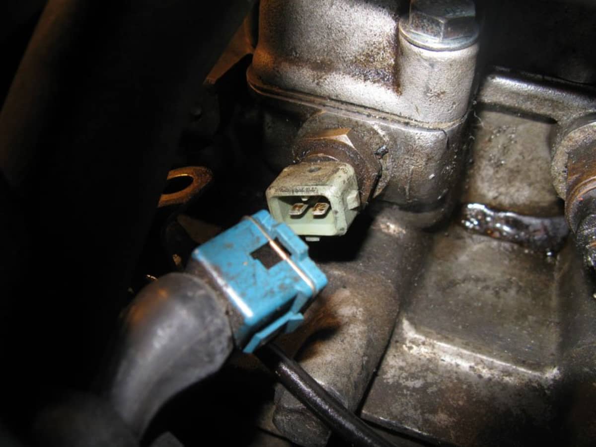
Grasp the wiring harness and lift it up and off of the thermostat. The wiring harness has two plastic tabs on the bottom of it that fit into mounting holes on the top of the thermostat. Reach down and unplug the oil pressure switch. You now have clear access to the MINI R56 coolant temperature sensor. Reach down and disconnect the temperature ...

Code No P0118 Engine Coolant Temperature Sensor Circuit High Input
Coolant Temp Sensor. THREAD: 1/8 NPT 27TPI. Part Number: HT-010304. USD $38.00. Buy in monthly payments with Affirm on orders over $50. Learn more. Availability: In stock - ready to ship. THREAD: 1/8 NPT 27TPI. INCLUDES: Matching male Deutsch DTM-2 Connector (HT-031000)

Techdoc
https://i0.wp.com/wiringforums.com/wp-content/uploads/2017/12/diagrams24261514-triumph-bonneville-wiring-diagram-triumph.jpg?fit=800%2C600&1
Toyota Corolla Repair Manual Circuit Description Engine Coolant Temperature Circuit Sfi System Diagnostics
But with the wire color discrepencies, I'm not sure the schematic is right... and I don't want to hook it up wrong and fry something else...
How Automotive Engine Coolant Temperature Sensors Work
... that is (Coolant Temperature Sensor Wiring Diagram Awesome) Many people searching for details about(Coolant Temperature Sensor Wiring Diagram Awesome ...

Engine Coolant Temperature Ect Sensor Inspection Zj Z6 Mazda Mazda3 1g 2007 Diy Repair Guide
On 1st gen auto 12v's there is what you are referring to. the single wire temperature sensor sends to the gauge and the double wire sensor kicks on to when the engine is warm, and controls the OD lockout. it is about 4 -5" to the rear of the engine from the intake air temperature sensor. on first gens it has 2 wires one white one blue.
Coolant Temperature Sensor Resistance And Temperature Indication Subaru Outback Forums
The coolant temp sender for the gauge has one wire, dark green. That one is in the left cylinder head between the first two spark plus. The coolant temp sensor for the PCM has two wires and is located near the thermostat. Assuming this is not a diesel engine.
Audi Workshop Manuals A4 Mk1 Power Unit Motronic Fuel Injection And Ignition System 4 Cyl Turbo 07 96 Mixture Preparation System Electronic Inj Gas Testing Control Unit Input Values Testing Coolant Temperature Sensor
... Diagram 97 Grand Prix Coolant Temperature Sensor Wiring Diagram 2003 Polaris Sportsman 500 Fuse Box 1995 Dodge Ram Pcm Wiring Diagram 1949 Ford Custom ...
Subaru Legacy Service Manual Dtc P0118 Engine Coolant Temperature Sensor 1 Circuit High Diagnostic Procedure With Diagnostic Trouble Code Dtc

Toyota Sequoia Limited Toyota Sequoia 2004 Repair
Part 1 Troubleshooting P0117 And P0118 Ect Sensor Tests Ford 3 0l 3 8l
Kia Picanto Engine Coolant Temperature Sensor Ects Engine Control System
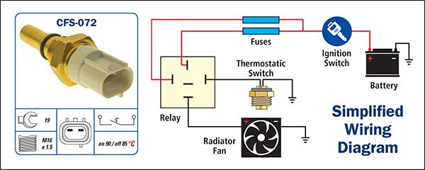
Cooling Fan Switches Cfs
/Page-225001.png)
Audi Workshop Manuals 100 Quattro Sedan L5 2309cc 2 3l Sohc Nf 1989 Sensors And Switches Sensors And Switches Cooling System Engine Coolant Temperature Sensor Switch Coolant Temperature

Shayne Pavey Autotronics 2 Ect Engine Coolant Temperature Sensor
Coolant Temperature Sensor Test Axleaddict
Toyota Avalon Service Repair Manual Engine Coolant Temperature Sensor 1 Circuit Short To Ground P011511 Sfi System

P0118 Engine Coolant Temperature Ect Sensor High Input Troublecodes Net

Solved On My 2000 Ford Ranger The Plug That Snaps Into Fixya
Water Temperature Sensors Wts
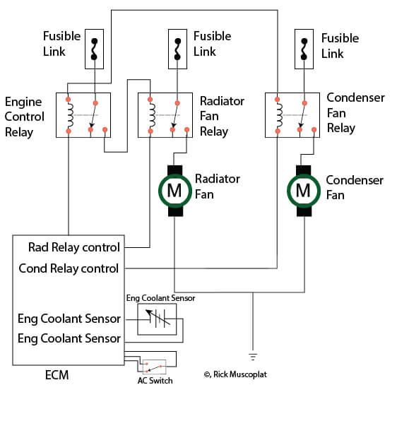
Hyundai Wiring Diagram Radiator Fans Ricks Free Auto Repair Advice Ricks Free Auto Repair Advice Automotive Repair Tips And How To
0 Response to "42 coolant temperature sensor wiring diagram"
Post a Comment