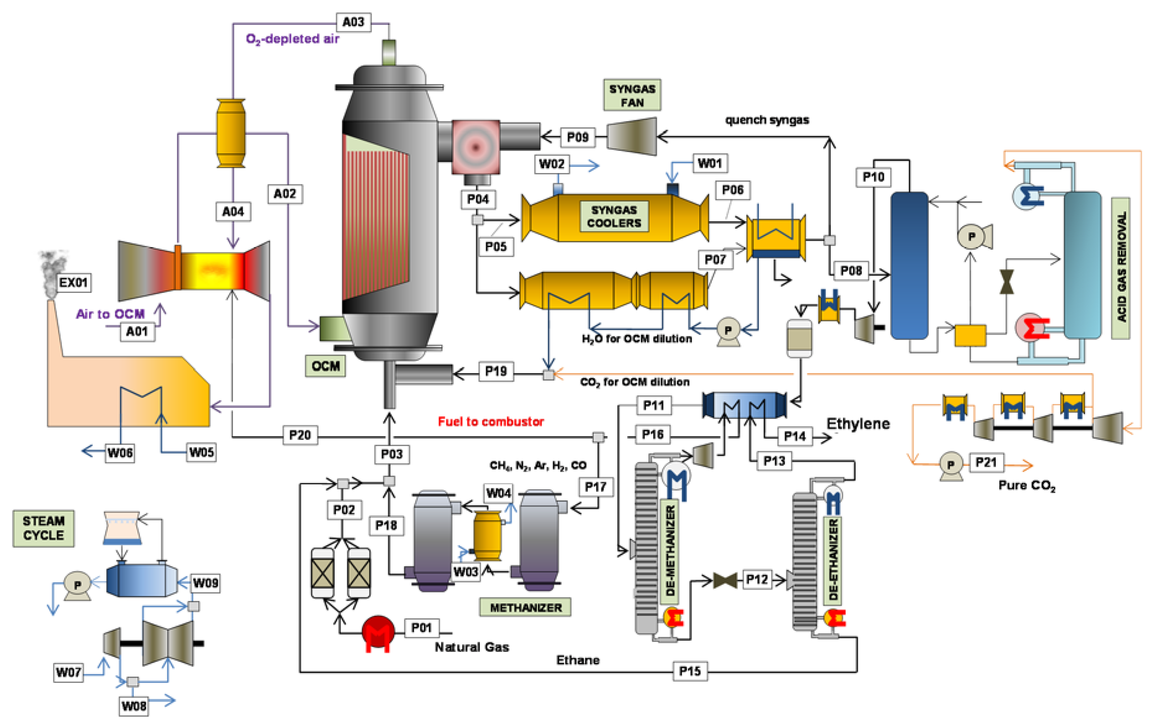
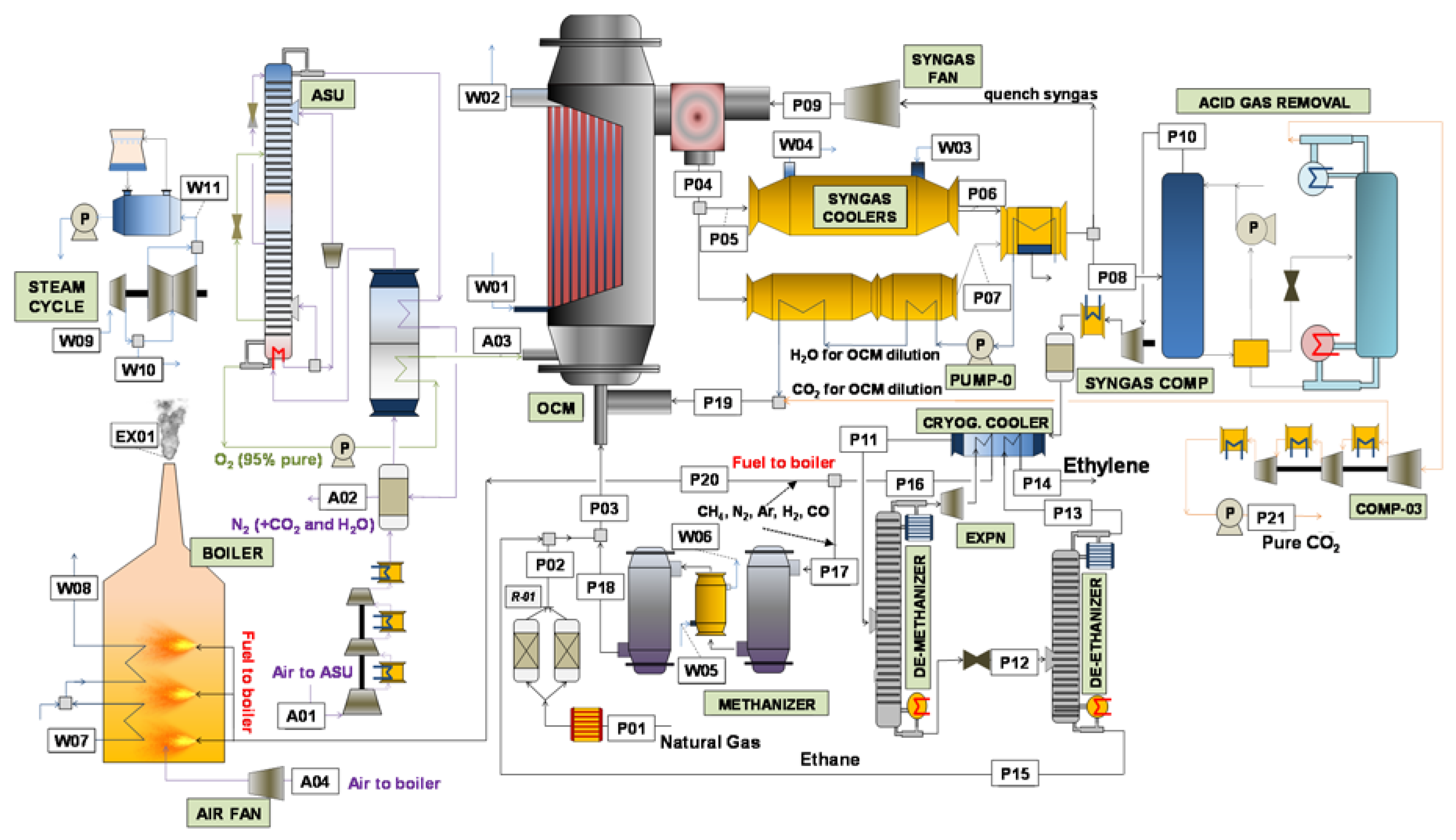
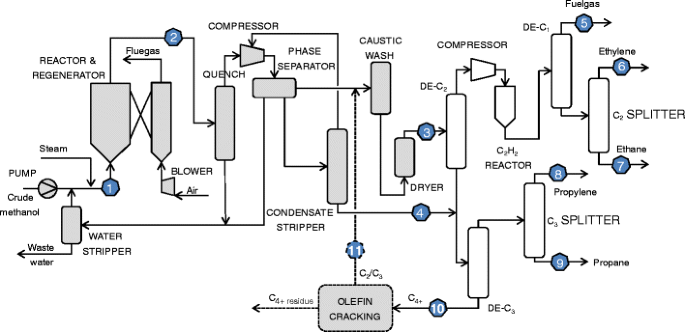
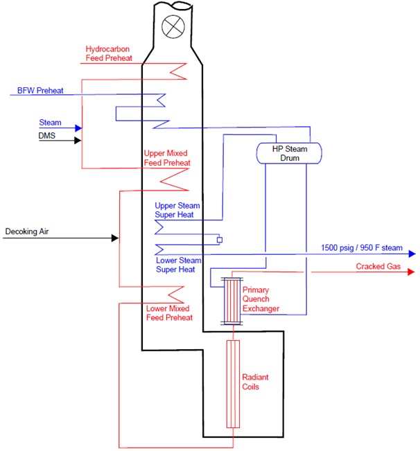
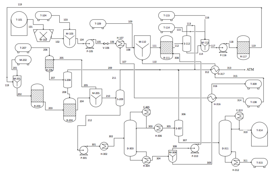
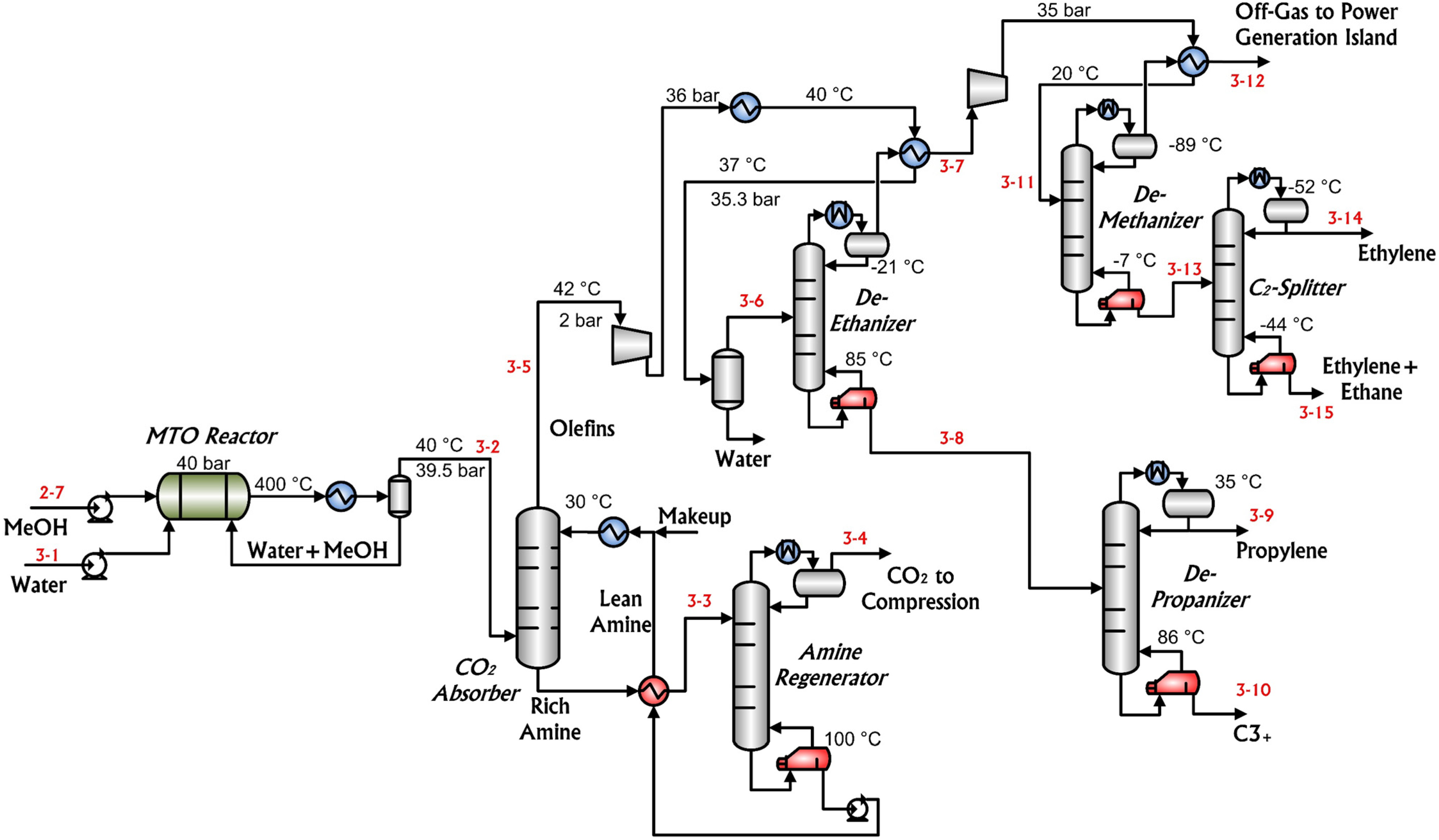
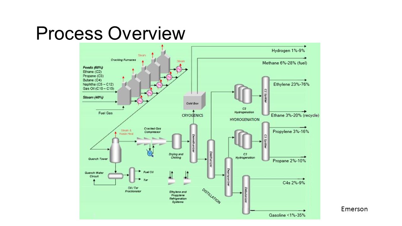
42 ethane cracker process flow diagram
cracking, including a 50% reduction in capital costs (Figure ES-2), a 20% decrease in operating costs (Figure ES-3), a 77% reduction in process energy required, and a more than 70% reduction in carbon footprint. Figure ES-2. Comparison of capital costs for the ENDP and steam-ethane cracking. Ethane 111 tonne/hr Nuclear Steam 140 MWt Steam Cracking Process. A typical ethane cracker has several identical pyrolysis furnaces in which fresh ethane feed and recycled ethane are cracked with steam as a diluent. Figure 3-12 is a block diagram for ethylene from ethane. The outlet temperature is usually in the 800°C range.
The majority of ethylene is produced using a process called "steam cracking", a thermal process where hydrocarbons are broken down, or "cracked" into smaller molecules that are then used to manufacture more useful (and valuable) chemicals. In the petrochemical industry, two of the main feedstocks for steam crackers are naphtha and ethane.

Ethane cracker process flow diagram
The model was used to simulate the performance of propane and ethane cracking. The model predicted propane conversion is 95.55 against the plant data of 95% at a coil outlet temperature of 845 °C ... Appendix C—Process flow diagrams 139 . Tables . Table 2.1 Summary of ACO process economics 9 Table 2.2 Summary of cracking yields 9 ... Table 6.3a Ethylene from wide-range naphtha via downflow FCC process—Ethane cracking yields (wt%) 72 Advances in Ethane Cracking. Gabriel Castaneda, P.E. Gabchem Solutions. Linde (713) 873 1708. ... Ethane Cracker Process Flow Diagram. Chevron Phillips. Single ...
Ethane cracker process flow diagram. ETHYLENE — PROCESS FLOW DIAGRAMS Ethylene Steam Cracker Process Feed Furnace Section Feedstock Cracking Quench Separation Refrigeration Acid Gas Removal Compression & Condensation Steam Generation Ethylene Propylene Recycle Streams Fuel Gas Streams Quench Compression Decontamination Separation. For each iteration, the acetylene was hydrogenated, and then 100% of the ethane was recycled. This was repeated until the recycled ethane was extinct. These iterations were performed on Table 2.2: Furnace Product Stream Composition Component Mass Flow Rate (lb/hr) Mass Percent in Stream H 2 2,249 1.6 CH 4 26,409 18.9 C 2H 2 844 0.6 C 2H 4 ... The new facilities will process ethane to produce ethylene and other products. The ethane recovered from the process is recycled to the feed stream. A process flow sequence is shown on the block flow diagram, Figure 2-1. The proposed project will contain typical process equipment The steam cracking process is a cornerstone of the chemical industry as it generates highly valu-able olefins - from which ethylene, propylene and butadiene are the most relevant ones - from lower value feedstocks. Feedstocks for this process usu-ally have fossil origin and range from gaseous feedstocks, like ethane and propane, to liquid,
Cryogenic distillation columns are then used to isolate methane, ethylene, and ethane from heavier hydrocarbons (C3+). Methane and ethylene are sold as product, and ethane is recycled to the cracking furnace. Natural gas combustion within the furnace raises temperatures high enough to induce the cracking reaction that converts ethane to ethylene. with a multitude of applications. Ethylene itself is produced by thermally cracking ethane, a component of natural gas. The Lindgren Group has designed a process capable of producing 500 million pounds of ethylene per year from raw natural gas. Additional products such as interstate The proposed design consists of six main sections: acid gas removal, dehydration, fractionation train, hydrogenation reactor, an ethylene splitter and steam cracking (refer to Appendix B for the process flow diagram). Carbon dioxide must first be removed from the inlet shale gas in the acid gas removal section. Figure I: Ethane Cracker Schematic Diagram 19 CrEEer Fwnace i½at Recovery Operating an ethane cracker requires an enormous amount of energy. The furnace alone requires large amounts of energy in order to achieve the high temperatures needed for cracking; ethane is heated at temperatures above 15000 Fahrenheit (8000 Celsius).20 At the Beaver County
Figure 4 is a process flow diagram for the ethylene plant, which has two board operators using DCS. ... (2011) proposed an MINLP for scheduling of ethylene cracking furnaces system, which can consider the secondary ethane cracking, no simultaneous cleanup constraints and dynamic scheduling. Steam cracking furnaces are process units, devoted to producing ethylene and propylene from a stream of light hydrocarbons (e.g., light naphtha) and steam. These massive pieces of equipment are comprised of two key components, namely, a coil bundle, where the cracking reactions take place, and a furnace, which provides heat to the coils (recall that cracking reactions are endothermic). Figure 8: Process flow diagram of ethane steam cracking process.....42 Figure 9: Specific energy consumption of major sections- ethane cracking process.....49 Figure 10: Major energy contributors- ethane cracking process.....50 Figure 11: Block diagram of methane pyrolysis using partial oxidation method of heat ... pipeline. The ‘cracking’ process refers to the thermal breakdown of large complex organic molecules, such as ethane, into smaller organic constituents, such as ethylene and propylene. A process flow diagram for the Ethane Cracker Plant is presented in Figure 2-1, which outlines all
The ethane is fed to five cracking furnaces to heat the ethane to cracking temperature. To reduce coke formation in the cracking furnace tubes, a sulfide material is added continuously to the ethane feed. The concentration of sulfide material in the ethane feed is maintained at low ppm levels.
production are naphtha and natural gas (ethane, propane, butane, etc.). The first step in the production of ethylene is to take the feedstock and crack it into ethylene and other various products in a furnace. This process is called pyrolysis. Pyrolysis is the thermal cracking of petroleum hydrocarbons with steam, also called steam cracking.
Process flow diagram for ethane crackers (areas in red are not needed in ethane plants) ... Light olefins are conventionally produced by the steam cracking of hydrocarbons from ethane to gas oil ...
Processes Free Full Text Oxidative Coupling Of Methane In Membrane Reactors A Techno Economic Assessment Html
Figure 15 Block flow diagram for 100% ethane steam cracking 27 Figure 16 Input/output diagram for 100% ethane steam cracking 32 Figure 17 Simplified naphtha steam cracker block flow diagram 34 Figure 18 Coal-to-ethylene simplified block flow diagram 44 Figure 19 Primary forms of commercial coal gasifiers 52
Ethylene Process by Technip. To produce polymer-grade ethylene and propylene, a butadiene rich C4 cut, an aromatic C6-C8 rich raw pyrolysis gasoline and a high-purity hydrogen by steam pyrolysis of hydrocarbons ranging from ethane to vacuum gasoils (VGOs). Progressive separation applied for concept in the fields either front-end or back-end ...

Investigation Of Ethylene Production In Naphtha Thermal Cracking Plant In Presence Of Steam And Carbon Dioxide Sciencedirect
Nov 01, 2015 · This process diagram shows an ethylene-production process via the cracking of an ethane-propane mixture Cracking and quenching. Initially, an ethane-propane mixture is fed to furnaces in which, under high-severity conditions, it is cracked, forming ethylene, propylene and other byproducts.
Ethane cracker process flow diagram. Regardless of the process type all plants require process analytical equipment to collect reliable and accurate process data for process con trol product quality and plant safety. Normal operation assumes five furnaces continuous operation and one furnace on hot stand by or decoking operations. Advances in ...
• Strongly endothermic process Ethane • Absorbed duty: Q ~1.6 MW / ton of feed • For 1500 kta cracker: fired heat ~ 890 MW Naphtha ... Feed Products Heat. 12 Cracking Reactions - Products Example – ethane cracking C 2H 6 CH 3* + CH 3* initiation reaction CH 3* + C 2H 6 CH 4 + C 2H 5* hydrogen abstraction C 2H 5* C 2H ... Swirl Flow Tube ...
Jan 28, 2016 · Process flow diagram for ethane cracking. In the convection zone hydrocarbon feed stock. Image courtesy of cbi in ethane cracking fresh feedstock and recycled ethane are thermally cracked in the presence of steam in a bank of pyrolysis furnaces. Ethylene from renewable sources. Simulation and analysis of ethane cracking process.
Processes Free Full Text Oxidative Coupling Of Methane In Membrane Reactors A Techno Economic Assessment Html
A process flow sequence is shown on the block flow diagram figure 2 1. The ethane crackers fuel consists of a mixture of recycled tail gas hydrogen rich and natural gas methane with a heating value of 523 btuscf. The cracking process involves breaking up the carbon and hydrogen molecules and rearranging them. In case of gas cracking separation ...
Lummus Technology's proprietary ethylene steam cracking process is the most widely-applied process for the production of polymer grade ethylene, polymer grade propylene and butadiene. The process is noted for its performance, including high product yield and energy-efficiency, low investment cost and operating reliability.
Low cost Ethane cracking has an advantage of 300 to 400 USD per t of Ethylene in produc- ... A process is offered by UOP / Hydro based on a special zeolithe catalyst. The process flow diagram is shown in Fig. 10. Linde Engineering
Figure C -1: Ethane Cracker Process Flow Diagram . C2 Cut . C2 . Splitter . Ethylene Storage Deethanizer Demethanizer . C3 . Splitter . Depropanizer. Gasoline . Debutanizer Storage . Raw C4 . Storage . C4 Cut . C5+ Acetylene Reactor . Ethane Recycle toFurnace . C3 Cut . Fresh Ethane . CGC . 5. th. Stage . Dryers & Spent Caustic . System . Pressure Swing Adsorption . Recycled H2
Advances in Ethane Cracking. Gabriel Castaneda, P.E. Gabchem Solutions. Linde (713) 873 1708. ... Ethane Cracker Process Flow Diagram. Chevron Phillips. Single ...
Appendix C—Process flow diagrams 139 . Tables . Table 2.1 Summary of ACO process economics 9 Table 2.2 Summary of cracking yields 9 ... Table 6.3a Ethylene from wide-range naphtha via downflow FCC process—Ethane cracking yields (wt%) 72
The model was used to simulate the performance of propane and ethane cracking. The model predicted propane conversion is 95.55 against the plant data of 95% at a coil outlet temperature of 845 °C ...

Simulation And Dynamic Optimization Of An Industrial Naphtha Thermal Cracking Furnace Based On Time Variant Feeding Policy

Thermal Catalytic Cracking Of Hydrocarbons For The Production Of Olefins A State Of The Art Review Iii Process Modeling And Simulation Sciencedirect

A Look At The Industrial Production Of Olefins Based On Naphtha Feed A Process Study Of A Petrochemical Unit Intechopen
Light Olefins And Transport Fuels From Biomass Residues Via Synthetic Methanol Performance And Cost Analysis Springerlink

.jpg)










0 Response to "42 ethane cracker process flow diagram"
Post a Comment