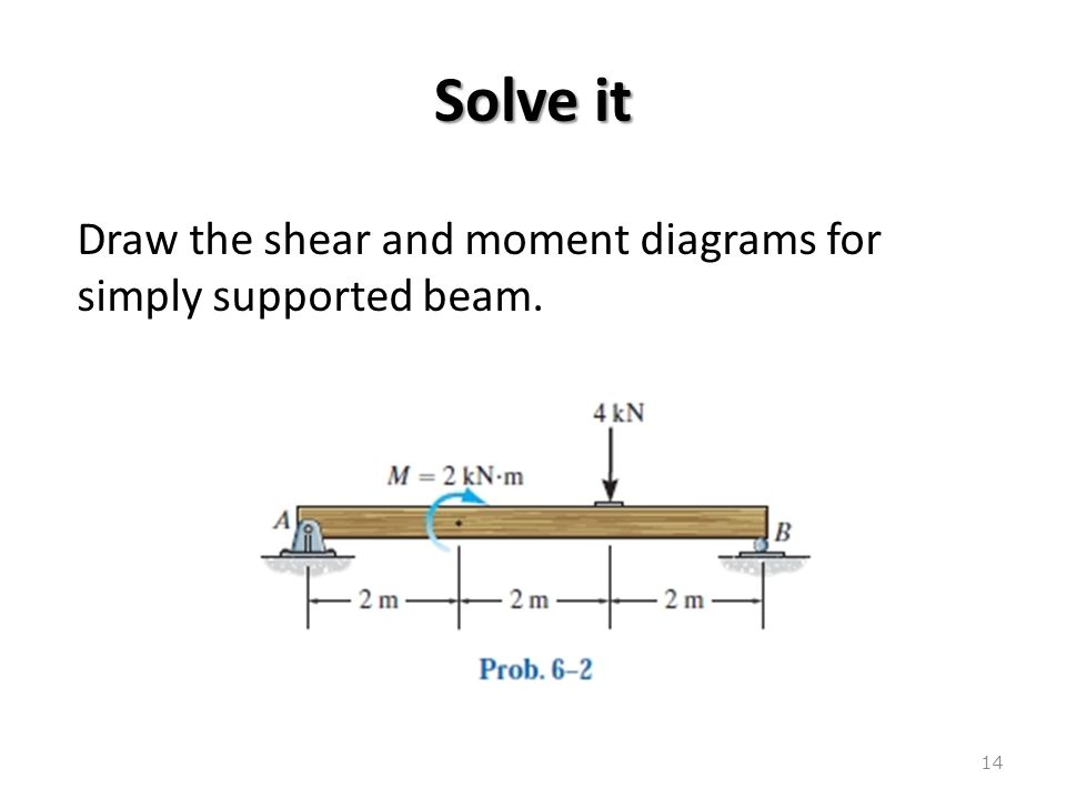
42 shear moment diagram example
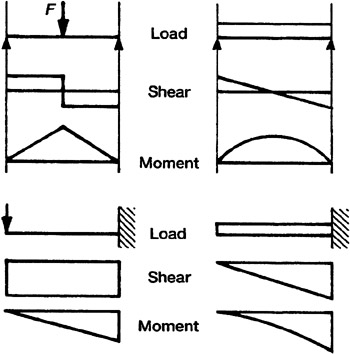
Examples: Level 1: Single Point Load. This is example shows how to use the steps outlined in the "Steps" tab to draw shear force and bending moment diagrams. Level 2: Distributed Force. This example deals with a constant distributed force (shear is a linear function of x). Level 3: Point Moment. In this example, the point moment causes no shear ... internal shear force, V, off of the shear diagram. We also already calculated the moment of inertia for this particular section. The remaining problem is that of calculating Q and t. Calculating Q(y 0) Hide Text 6 Generally, the most time consuming part of determining the shear stress in a beam is calculating the value of Q(y o
Statics of Bending: Shear and Bending Moment Diagrams David Roylance Department of Materials Science and Engineering Massachusetts Institute of Technology
Shear moment diagram example
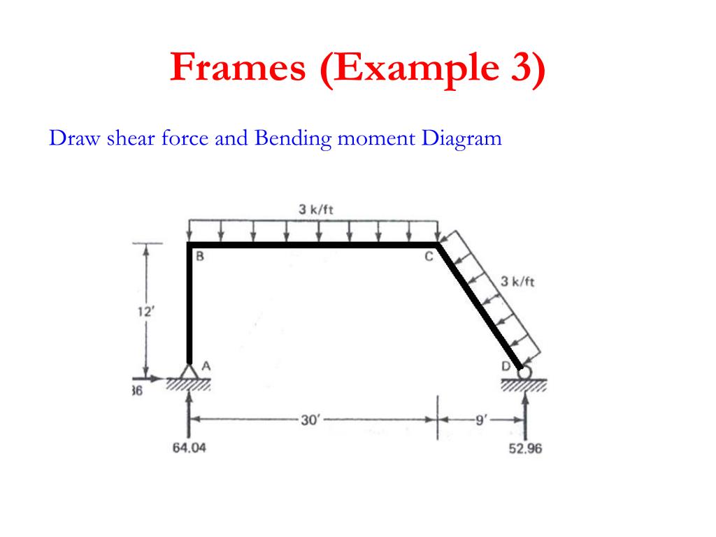
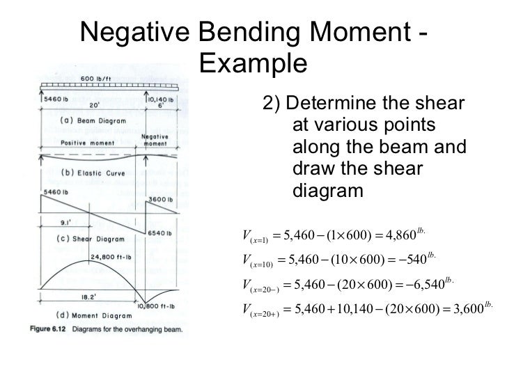
CE 331, Fall 2007 Shear & Moment Diagrams Examples 3 / 7 max MD = 16.0k-ft at Support 2 3. Calculate the max. moment due to live load (ML) at the location of the max. moment due to dead load (MD). 3.1 Determine where to place the live load to cause the max ML at the middle of Span 1. As mentioned on Page 1, the location of live loads is variable. S.F and B.M diagram (iv) Let us take an example: Consider a cantilever bean of 5 m length. It carries a uniformly distributed load 3 KN/m and a concentrated load of 7 kN at the free end and 10 kN at 3 meters from the fixed end. Draw SF and BM diagram. Page 131 of 429. Chapter-4 Bending Moment and Shear Force Diagram S K Mondal’s PDF_C8_b (Shear Forces and Bending Moments in Beams) Q6: A simply supported beam with a triangularly distributed downward load is shown in Fig. Calculate reaction; draw shear force diagram; find location of V=0; calculate maximum moment, and draw the moment diagram. 6k/ft 9 ft RA = (27k)(9-6)/9= 9k A B F = (0.5x6x9) = 27k x = (2/3)(9) = 6 ft
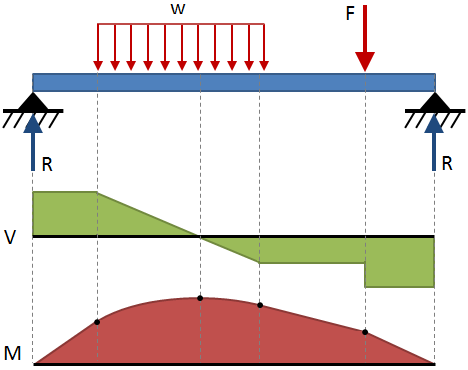
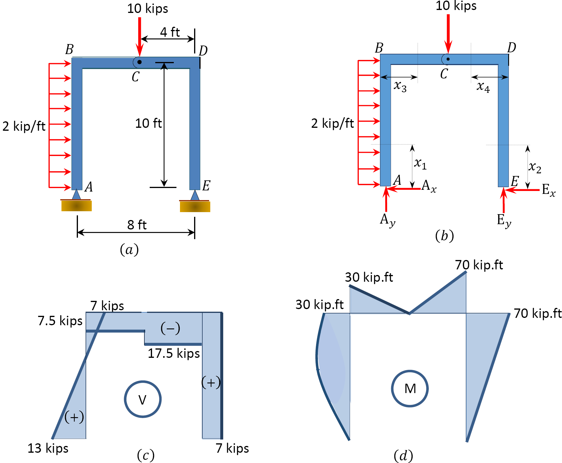
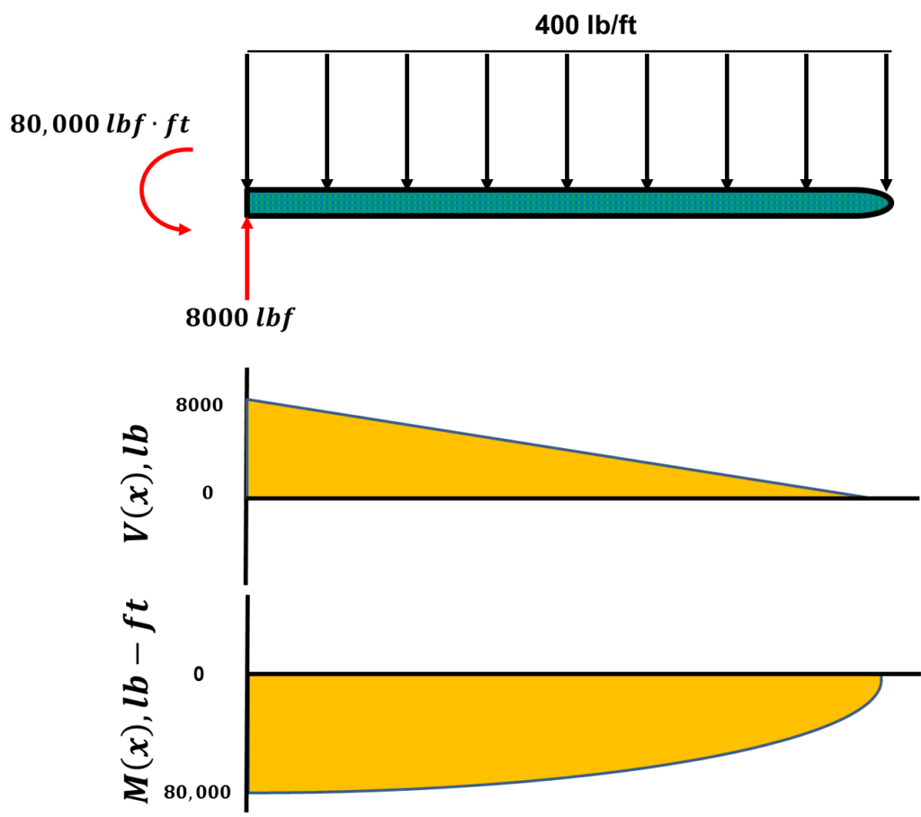
Shear moment diagram example. Example Problem Shear and Moment Diagrams Calculate and draw the shear force and bending moment equations for the given structure. 11 Sketching the Deflected Shape of a Beam or Frame Qualitative Deflected Shape (elastic curve) ≡ a rough (usually exaggerated) sketch of the neutral Q is a moment area with respect to the neutral axis of the area above or below the horizontal where the H occurs. Q is a maximum when y = 0 (at the neutral axis). q is a horizontal shear per unit length shear flow Shearing Stresses fv e = 0 on the beam’s surface. Even if Q is a maximum at y = 0, we Being able to draw shear force diagrams (SFD) and bending moment diagrams (BMD) is a critical skill for any student studying statics, mechanics of materials, or structural engineering. There is a long way and a quick way to do them. 4.0 Building Shear and Moment Diagrams. In the last section we worked out how to evaluate the internal shear force and bending moment at a discrete location using imaginary cuts. But to draw a shear force and bending moment diagram, we need to know how these values change across the structure.
PDF_C8_b (Shear Forces and Bending Moments in Beams) Q6: A simply supported beam with a triangularly distributed downward load is shown in Fig. Calculate reaction; draw shear force diagram; find location of V=0; calculate maximum moment, and draw the moment diagram. 6k/ft 9 ft RA = (27k)(9-6)/9= 9k A B F = (0.5x6x9) = 27k x = (2/3)(9) = 6 ft S.F and B.M diagram (iv) Let us take an example: Consider a cantilever bean of 5 m length. It carries a uniformly distributed load 3 KN/m and a concentrated load of 7 kN at the free end and 10 kN at 3 meters from the fixed end. Draw SF and BM diagram. Page 131 of 429. Chapter-4 Bending Moment and Shear Force Diagram S K Mondal’s CE 331, Fall 2007 Shear & Moment Diagrams Examples 3 / 7 max MD = 16.0k-ft at Support 2 3. Calculate the max. moment due to live load (ML) at the location of the max. moment due to dead load (MD). 3.1 Determine where to place the live load to cause the max ML at the middle of Span 1. As mentioned on Page 1, the location of live loads is variable.
Ppt Structure Analysis I Powerpoint Presentation Free Download Id 3372281

Asm Example 8 Structnotes

Drawing Shear Force Bending Moment Diagram File Exchange Pick Of The Week Matlab Simulink
How To Draw Shear Force And Bending Moment Diagram In Case Of Cantilever Beam Engineering Discoveries
Shear And Moment Diagram For Frame Question Physics Forums

How To Plot Bending Moment Diagram From Shear Force Diagram Engineering Stack Exchange

Shear Force And Bending Moment Diagrams This Website Gives A Useful Example Of How To Derive S Engineering Technology Civil Engineering Mechanical Engineering

Shear And Moment Diagram Wikipedia

Ultimate Guide To Shear Force And Bending Moment Diagrams Engineer4free The 1 Source For Free Engineering Tutorials

Shear Force And Bending Moment Diagram Practice Problem 1 Youtube
Moment Diagrams Examples

Drawing Shear Moment Diagrams Example Mechanics Of Materials And Statics Civil Engineering Downloads

Shear Force And Bending Moment Diagrams Along The Base Of The Footing Download Scientific Diagram
Hibbeler R C Structural Analysis
Bending Shear And Moment Diagram Graphical Method To Construct Shear Ppt Download
Beam Stress Deflection Mechanicalc
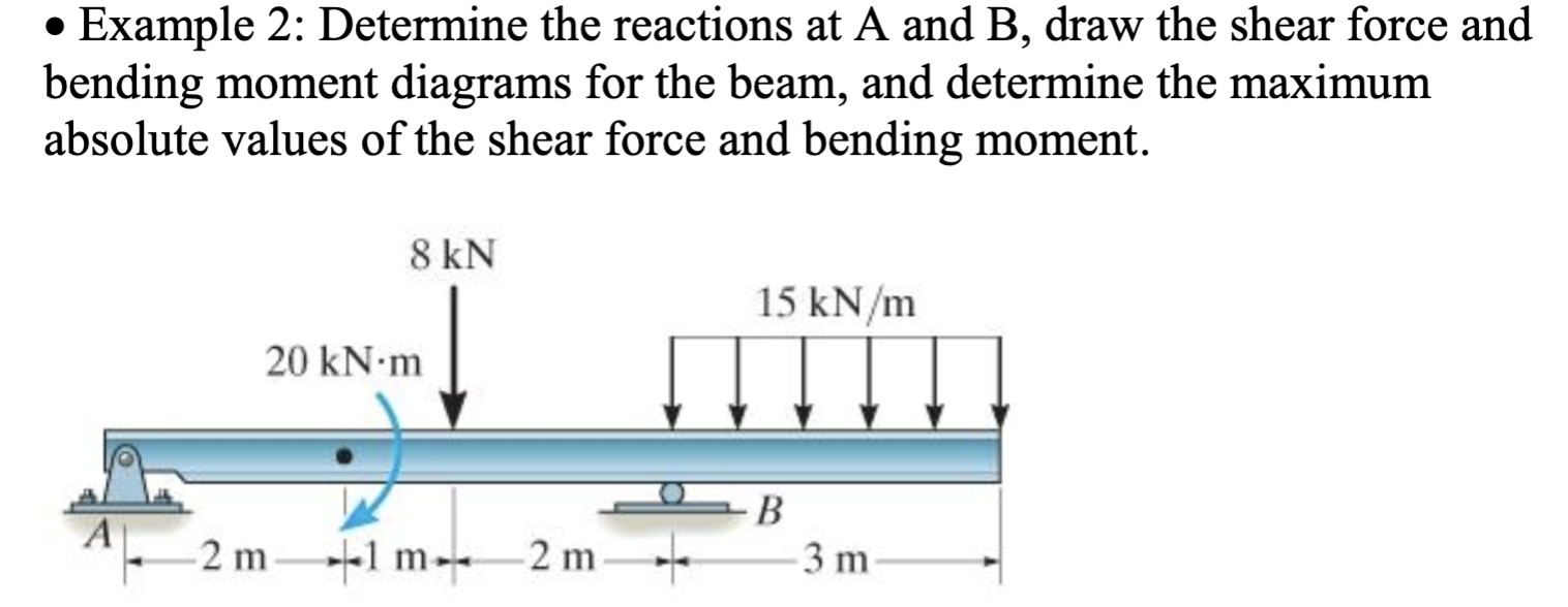
Solved Example 2 Determine The Reactions At A And B Draw Chegg Com
How To Draw Moment Diagrams Reviewcivilpe
Shear Force And Bending Moment Diagram For Overhanging Beam
Shear Force And Bending Moment Diagram For Cantilever

Statics Ebook Shear Moment And Load Relations

Shear Force Diagram An Overview Sciencedirect Topics
Solution To Problem 438 Relationship Between Load Shear And Moment Strength Of Materials Review At Mathalino

Moment Diagrams Examples

Chapter 8 Shear Force And Bending Moment Diagrams For Uniformly Distributed Loads Pdf Free Download
Lo Unisa Edu Au

Moment Diagrams Constructed By The Method Of Superposition Mo Civil Engineering
4 4 Relation Among Distributed Load Shearing Force And Bending Moment Engineering Libretexts
Structural Analysis Of A System Under Inertial Loads Shear And Bending Moment Diagrams Top Dog Engineer
Shear And Moment Diagrams
Determining The Shear Force And Bending Moment Equations Of Simply Supported Beam

Drawing Shear And Moment Diagrams For Beam Youtube
Shear Load And Bending Moment Diagrams
Moment Diagram Engineering360
21 B Example 18 For The Given Frame In 22 A Draw The Normal Shear Download Scientific Diagram

Bending Moment Diagram An Overview Sciencedirect Topics

Shear And Bending Moment Diagrams For Frames Construction How
Web Ncyu Edu Tw

Drawing Shear Force Bending Moment Diagram File Exchange Pick Of The Week Matlab Simulink

Bending Moment And Shear Force Diagram For Overhanging Beam Bending Moment Shear Force Structural Analysis

Moment Diagrams Constructed By The Method Of Superposition Mo Civil Engineering

Mechanics Ebook Shear Moment Diagrams
0 Response to "42 shear moment diagram example"
Post a Comment