43 double pulley system diagram
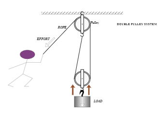
In this diagram, the pulley attached to the weight actually consists of two separate pulleys on the same shaft, as shown on the right. This arrangement cuts the force in half and doubles the distance again. To hold the weight in the air you must apply only 25 pounds of force, but to lift the weight 100 feet higher in the air you must now reel ... The pulley to the left is suspended and as a consequence the mechanical advantage is increased. This happens because the rope on the left and right of the pulley are both lifting the LOAD, they each lift half its weight. The load is split into 2. The calculation is shown below. Velocity Ratio (sometimes called movement ratio)- is defined as the ...
hewittparts.com 3 Double Pulley For 3600lb. & Larger [L1P3D] - 3" double stack pulley is used on Hewitt 3600# and larger cantilever lifts.
Double pulley system diagram
2. The double pulley system shown in Figure 5.89 has an inner radius of rį and an outer radius of r2. The mass moment of inertia of the pulley about point O is lo. A translational spring of stiffness k and a block of mass m are suspended by cables wrapped around the pulley, as shown. Draw the free-body diagram and kinematic diagram, and derive ... How to diagram a pulley system! Anchor point The anchor point should be a solid black box fixed to a surface. Dot Draw a large dot to show where the end of the rope is connected. Rope Use a nice black line to represent the ropes. Pulley Use a larger circle with a dot in the middle to represent the pulley. You can use a sticker to represent your pulleys Load Use the same symbol we used for load with levers. When we build a mechanical advantage system to move a load in this situation, a simple "Block and Tackle" system such as a 2:1 "Ladder Rig" or a 4:1 with double pulleys at the top and bottom can be used. Compound Pulley Systems. Compound pulley systems are created when a simple pulley system is pulling on another simple pulley system.
Double pulley system diagram. Humans use compound pulleys all the time. They are based on the work-energy principle. Here is a physics based explanation of this type of simple machine. The Speed Ratio is the ratio of angular velocity of the input pulley of a system to the angular velocity of the output pulley. If you've calculated gear ratios, it is almost exactly the same! This is all based on a pulley's reference diameter, as defined below: Reference/Pitch Diameter: The working diameter of the pulley, where the belt or cable contacts the pulley. 4:1 System. Four-to-one systems are less popular than 3:1 systems, probably because they require an additional pulley and don't offer significantly more mechanical advantage. However once you learn how to stack a 2:1 on a 2:1 to create a compound 4:1, you'll know how to stack a 2:1 on a 3:1 to create a 6:1 (also a less-popular system, but worth knowing if you are a rigging geek) and how to ... Therefore if the above pulley system carries n number of pulleys then VR = 2n. And MA = W/P (standard equation) Also efficiency ɳ = MA/VR. Second System of Pulleys. The diagram below shows the second system of pulleys consisting of two blocks. The upper block carries three wheels which freely rotate about their individual central axes and are ...
All in all, block and tackle pulleys are a smart, efficient, and cost-effective way to lift heavy objects. It is widely being used in many fields and has eased the tasks of lifting heavy objects. Block and tackle can be simulated via a diagram that can be drawn with many tools available on the internet. The string is wrapped around a pulley that changes the direction that the force is exerted without changing the magnitude. As an illustration of how a pulley works, consider the diagram at the right. Object A is connected to object B by a string. The string is wrapped around a pulley at the end of a table. Jan 03, 2018 · When the pulley is fixed to a solid anchor and a rope is threaded through the grooves on the pulley's wheel, it can be used to lift heavy weights much more easily than doing it by brute force. And you can double the effectiveness of a pulley system by increasing the number of pulleys in the setup. Pulley systems are used to provide us with a mechanical advantage, where the amount of input effort is multiplied to exert greater forces on a load. They are typically used for hauling and lifting loads but can also be used to apply tension within a system such as in a Tensioned Line or Tyrolean. This page explains the basic principles of ...
Figure 5.6: A diagram for the system of two objects and a pulley. Figure 5.7: Free-body diagrams if there is no friction. (a) The free-body diagram of the red box. (b) An appropriate coordinate system for the red box. (c) The free-body diagram of the red box, with force components aligned with the coordinate system. (d) and (e), a Nov 8, 2016 - Reeving blocks to set up a double pulley system requires a little thought. A double pulley system, also known as a "block and tackle," consists of the pulleys, or blocks, and the tackle, the ropes riven through the blocks. You must decide if you will use a double pulley system with one sheave--the roller in a ... Jul 24, 2019 · The 2:1 Pulley System. If we take a 1:1 system and turn it upside down it will result in a 2:1 mechanical advantage. Instead of the pulley being attached to an anchor it is now attached to the load (pulley A). On one side of pulley A the rope has been attached to a fixed anchor point, the rope on the other side of pulley A has been sent back ... Meaning, if one pulley is standing vertical, the other pulley must be standing vertical as well. The reason for this is because of how the ropes sit inside the pulley system. There isn't any room for the pulleys to rotate with respect to each other. Some drawbacks of the right-to-left reeving method are that you get uneven loading on your rope.
Nov 2, 2016 - Reeving blocks to set up a double pulley system requires a little thought. A double pulley system, also known as a "block and tackle," consists of the pulleys, or blocks, and the tackle, the ropes riven through the blocks. You must decide if you will use a double pulley system with one sheave--the roller in a ...
If the rope used in the pulley system is tied to the LOAD, the ideal mechanical advantage (IMA) will be ODD (i.e., 1:1, 3:1. 5:1, etc.) Even if a change of direction at the anchor does add friction, it might make your pull easier, depending on your own personal strength, body weight, and the weight of the load you need to move.
Double pulley system diagram. A double pulley system , also known as a "block and tackle," consists of the pulley s, or blocks, and the tackle, the ropes riven through the blocks. You must decide if you will use a double pulley system with one sheave--the roller in a pulley --in each block, which will give you a mechanical advantage of 3 to 1 ...
A double pulley system, also known as a "block and tackle," consists of the pulleys, or blocks, and the tackle, the ropes riven through the blocks. You must decide if you will use a double pulley system with one sheave--the roller in a pulley--in each block, which will give you a mechanical advantage of 3 to 1, or a double pulley system with two sheaves in each block, which will give you a mechanical advantage of 5 to 1.
The pulley system below features 300 N of load and three pulleys: What weight is needed to pull the load? Reveal answer. Three sections of rope are taking the strain of the load.
Draw the free-body diagram and kinematic diagram, and derive the equation of motion using; Question: The double pulley system shown in Figure 5.86 has an inner radius of r_1 and an outer radius of r_2. The mass moment of inertia of the pulley about point O is I_o.
American made products designed for climbers, mountaineers, arborists, ropes course professionals, and fire service and industrial safety experts.
3:1 System The 3:1 is the classic mechanical advantage system used by rescuers. It requires less rope than a (non-piggybacked) 2:1 system, is reasonably easy to rig, is easy to add a progress capture device, provides an appropriate amount of mechanical advantage to raise one or two people, and with a few tweaks it can be converted into a simple 5:1 system .
This engineering statics tutorial goes over how to calculate tension in a multiple pulley system that is in static equilibrium. There are 4 cables, 3 pulleys...
http://www.physicshelp.caGO AHEAD and click on this site...it wont hurt.Free simple easy to follow videos all organized on our website
A simple pulley system, where the end of the line is attached to the anchor, has the mechanical advantage, which is equal to 2n where n is the number of moving pulleys. Here F A is the anchor load, F E is the effort force and F L is the load. For example, if there are four moving pulleys and 8 lines (the most left line is used only for change of direction) the MA = 8.
When we build a mechanical advantage system to move a load in this situation, a simple "Block and Tackle" system such as a 2:1 "Ladder Rig" or a 4:1 with double pulleys at the top and bottom can be used. Compound Pulley Systems. Compound pulley systems are created when a simple pulley system is pulling on another simple pulley system.
How to diagram a pulley system! Anchor point The anchor point should be a solid black box fixed to a surface. Dot Draw a large dot to show where the end of the rope is connected. Rope Use a nice black line to represent the ropes. Pulley Use a larger circle with a dot in the middle to represent the pulley. You can use a sticker to represent your pulleys Load Use the same symbol we used for load with levers.
2. The double pulley system shown in Figure 5.89 has an inner radius of rį and an outer radius of r2. The mass moment of inertia of the pulley about point O is lo. A translational spring of stiffness k and a block of mass m are suspended by cables wrapped around the pulley, as shown. Draw the free-body diagram and kinematic diagram, and derive ...


0 Response to "43 double pulley system diagram"
Post a Comment