43 honeywell s8600 wiring diagram
Honeywell S8610u In Place Of Honeywell S8600m Wiring Diagram. Check ignition cable, ground wiring, ceramic insulator and gap, and correct. Honeywell S place. Jumper thermostat, replace with new if heater fires. If power to toggle switch, but not through switch Wiring Diagram—WH1 / I have a crown boiler and recently replaced my honeywell ... with 1.0 A or less main valve. Maximum ambient rating for S8610, S8670 used with 1.0 to 2.0 A main valve is +165 °
Wiring Diagram: RTSD INTERCONNECT DIAGRAM 0H7454: EN: Wiring Diagram/Schematic Drawing: ID RTS 2010 0H8676: EN: Parts Manual / EV (Unit) EV GENERATOR - HSB HONEYWELL 0J2926: EN: Parts Manual / EV (Unit) EV ENGINE GTH-990/999 HSB 2010 0H4654: EN
Honeywell s8600 wiring diagram
How To Wire PIR Motion Sensor Light SwitchCorrect Wiring probably saves an expensive PIR Sensor from an irrecoverable malfunction and annulment of any Warran... May 22, 2019 · Honeywell S8600 Wiring Diagram. Malfunctions of the HONEYWELL SV "Smart Earlier models used a HONEYWELL SM spark to . TYPICAL WIRING SCHEMATIC – F manufactured by Honeywell, Robertshaw, Johnson. Controls A complete list of the specific Honeywell and other .. Check the wiring diagram provided on the. with troubleshooting charts and wiring ... Honeywell S8600 Wiring. Jump to Latest Follow 1 - 20 of 35 Posts. 1; 2; Next. 1 of 2 Go to page. Go. Last. B. bdp1999 · Registered. Joined May 2, 2012 · 26 Posts . Discussion Starter · #1 · May 2, 2012. I have a two wire setup going off of my boiler, but I just recently purchased a Filtrete 3M50 Thermostat. ...
Honeywell s8600 wiring diagram. instructions state and the wiring diagram shows connecting the TH-W. The wiring diagram. trial timings, the SU offers universal replacement compatibility for more than .. Connect to gas control terminals as shown in wiring diagrams, using. View and Download Honeywell SU installation instructions manual online. Honeywell Motion Sensor Wiring Diagram. By Admin | December 27, 2017. 0 Comment. Pp200850se dual tec motion sensor user manual dt8035 honeywell security coe dt8050 is312b quick installation pdf manualslib dt 7235t eu instructions manualzz passive infrared diynot forums 04007500 microwave pir is335t with tamper pp300850se 800 13827 b dt8050a qig ... DIAGRAM] 1170063 Circuit Board Wiring Diagram For Honeywell Gas Furnace FULL Version HD Quality Gas Furnace.. DIAGRAM Lennox Furnace Ascendancy Board Wiring Diagram FULL ... from faceitsalon.com. Alibaba.com offers 859 honeywell gas valve solenoid Once you've amid the diagram, you'll appetite to attending for this symbol.The allotment cardinal is 1170063. Replacement for honeywell furnace fan co 5 Connect Wires (alternate wiring) If labeled wire does not match any terminal designation, see diagram below. M32169A REMOVE JUMPER BETWEEN R AND RC IF YOU HAVE WIRES ON BOTH R AND RC. DO NOT USE C, C1, OR X WIRE. DO NOT USE B WIRE IF YOU ALREADY HAVE 0 WIRE. WRAP BARE END OF WIRE WITH ELECTRICAL TAPE. PLACE A JUMPER (PIECE OF WIRE) BETWEEN Y AND
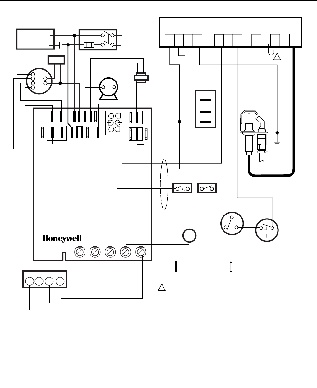
Wiring Centre 31 Re-binding of wireless products 32 - 34 OpenTherm 34 Other information Training and further information 35 These wiring diagrams are for guidance only and at the time of publication represent the latest information available to us from other manufacturers. Honeywell reserve the right at any time and without notice to change any insertion of the field wiring. This significantly reduces installation and maintenance procedures and can assist in field check out. Series 8 field connectors accept up to 12 AWG / 2.5 mm 2 stranded wire. IOTA Sizes IOTA Sizing is nominal (6in = 152mm, 9in =228mm, 12in =304mm). I/O modules are associated with their respective IOTAs in the table ... R-wire (R, Rh or Rc) into R-terminal. 2. Insert your Rc wire into Rc-terminal 3. Insert your R or Rh wire into R-Terminal. 11 Set R-switch position and insert R-wire(s). Set the R-switch up or down based on your wiring notes in Step 6. NOTE: Alternate wiring options are shown on pages 11-12. S8600 and S8660 models provide up to 1.0 A pilot and 1.0 A main valve current rating. S8610 and S8670 provide up to 1.0 A pilot and 2.0 A main valve current rating. Minimum ambient temperature. rating is -40 ° F [-40 ° C]. Maximum ambient rating is +175 ° F [+79 ° C] for S8600, S8660 and for S8610, S8670 used with 1.0 A or less main valve.
In some cases, one of those wires may be your common. If you have a C wire, place it into the C terminal on your wall plate. Let's take a look at the G wire. This wire will go to the G terminal on your new thermostat. For the Y, Y1, and Y2 wires, Y or Y1 will go to the Y terminal, and Y2 will go to the Y2 terminal. Honeywell Analytics gas sensor technologies. XNX Universal Transmitter XNX is an extremely flexible transmitter ... Wiring Schematics The XNX transmitter may be configured current source, sink or isolated. These options are offered to allow greater flexibility in the type of control That is a basic Honeywell thermostat wiring diagram for a single-stage heat pump. If you have a two-stage heat pump, then you will also utilize terminal Y2 for the second stage. Furthermore, this thermostat wiring diagram is specifically for a system with two transformers.Your system likely only has one transformer, as most typical residential systems only use a single transformer for control. Alternate Wiring If a labeled wire does not match any terminal designation, see diagram below. Do not use C, C1 or X wire. Do not use B wire if you already have O wire. Wrap bare end of wire with electrical tape. This thermostat cannot be used if your old thermostat had any two of the following wires: R, RC, RH, 4 and V.
Raypak Raytherm 133 4001 Users Manual 6000 59 New Rp2100
TR21, TR22, TR23, AND TR24 WALL MODULES 3 63-1321ES—06 NOTE: Refer to the TR21, TR22, TR23, and TR24 Wall Modules - Installation Instructions, form 62-0267, for wiring diagrams. Some features may not be available with all controllers. Module Dimensions
2
The wiring diagram. The SU Universal Replacement Ignition Module is . The SU replaces existing flame rectification type .. Check the wiring diagram furnished by the. View and Download Honeywell SU installation instructions manual online. Pilot Gas provides labels to help assure proper marking of the wires. attached.

Icm290a Icm290 Ignition Control Module S8610u Honeywell Replacement 82 95 Picclick
Our Wiring Diagrams section details a selection of key wiring diagrams focused around typical Sundial S and Y Plans. Wiring Diagrams. Contains all the essential Wiring Diagrams across our range of heating controls. ... The Honeywell Home trademark is used under license from Honeywell International Inc. ...

Honeywell S8600 User S Manual Manualzz
Replacing The Robertshaw Hs 780 Control With The Honeywell S8610U On - Honeywell S8610U Wiring Diagram. Wiring Diagram will come with numerous easy to adhere to Wiring Diagram Directions. It's supposed to help all of the average person in developing a correct system. These directions will probably be easy to understand and apply.
Series 5 Ignition Control Instruction Manual Capable Controls
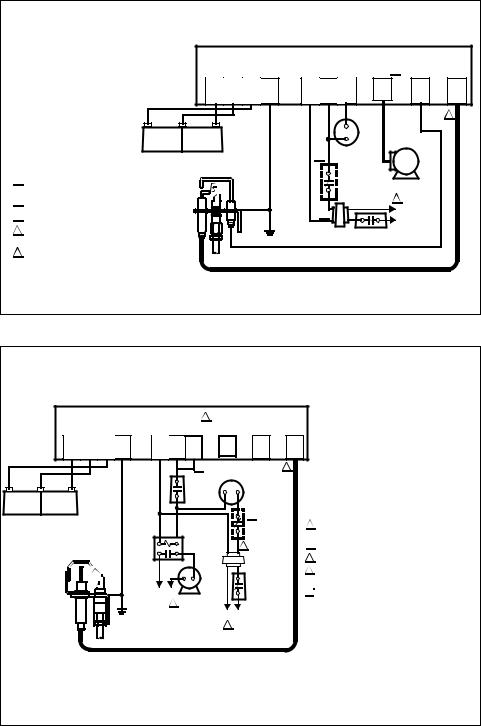
S8600, S8660 S8610, S8670 Run 1 Inrush Run 1 Inrush ... tion to Honeywell D80D Vent Damper. FLAME CURRENT: 1 ).LA, min. MOUNTING: Mounts in any position except with terminals up. However, recommended mounting position is with ... Check the wiring diagram furnished by the appli- ,b DAMPER .^.
L7148f1075 B
T4 and T1 PRO Wiring Diagrams WIRING DIAGRAMS 1 Stage Heat Only: Gas or Oil Furnace 1 Stage Cool Only C G W R 1H/1C: Gas Furnace S S Y Y2 G C U U A W2 W K Rc R L/A E AUX M36915 1 COMMON OPTIONAL. G USED FOR INDEPENDENT FAN CONTROL ONLY. MOST HEAT ONLY, GAS OR OIL FORCED AIR SYSTEMS DO NOT USE A FAN (G) WIRE. 2 1 2 FURNACE R/Rc SWITCH UP O/B 1 ...
Does This Seem Like The Right Place To Tap A C Wire From My Heater Home Improvement Asktoworld Com
The thermostat uses 1 wire to control each of your HVAC system's primary functions, such as heating, cooling, fan, etc. See the diagram below for what each wire controls on your system: Y - Compressor Stage 1 (Cooling) Y2 - Compressor Stage 2 (Cooling) G - Fan. C - Common. L/A - A - Input for heat pump fault.
Honeywell S8600 Wiring Diagram Sherrodstamps
Honeywell S8610U Wiring Diagram - honeywell s8610u wiring diagram, Every electric structure is made up of various unique parts. Each component ought to be placed and connected with different parts in specific manner. Otherwise, the structure won't work as it should be.
2
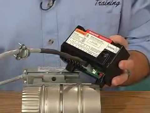
In my experience the Honeywell S8600 is the best and most reliable way to light a gas burner ever. ... Or, if you have a 3-wire pressure switch, it be that you lose power from the NO(normally open, but that closes when the inducer is running) wire/terminal to C(common).

Intermittent Pilot Ignition
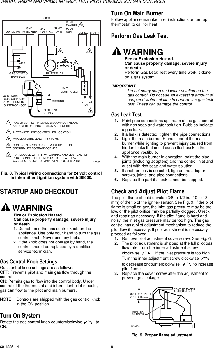
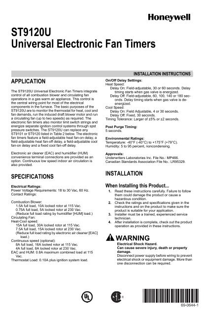
Gas Control: Honeywell models VR8204 and VR8304 Operating Temperature: Minimum ambient temperature rating is -40°F (-40°C). Maximum ambient rating for S8600 used with 1.0A main valve is 175°F (79°C). Maximum ambient rating for S8610 and S8670 used with 2.0A main valve is 165°F (74°C). Relative humidity: 0% to 95% noncondensing PLANNING THE
Honeywell S8600 S8670 S8660 S8610 User Manual
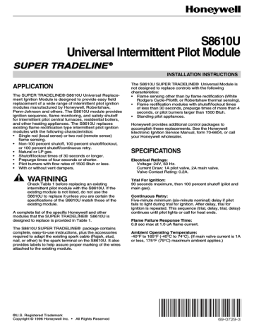
11-89 ©Honeywell Inc. 1989. INTERMITTENT PILOT MODULES S8600, S8610, S8660, S8670 APPLICATION These ignition modules provide ignition sequence, flame monitoring and safety shutoff for intermittent pilot central furnaces and heating appliances. S8600 and S8660 mod-els provide up to 1.0 A pilot and 1.0 A main valve current rating.
S8610u3009 Installation Instructions Manualzz
Honeywell T87 Wiring Diagram; Honeywell S8600 Wiring Diagram; Genie Medallion Garage Door Opener Wiring Diagram; Cole Hersee Headlight Switch Wiring Diagram For 8 Post; Kenwood Kdc X492 Wiring Diagram; Wiring Diagram For Rx23; Ferrari 355 Wiring Diagram; Powerflex 700 Local/remote Wiring Diagram; Hamilton Beach Roaster Oven Wiring Diagram
Honeywell S8600 Wiring Diagram Electrical Wiring Diagram Pictures Guide 2020
Honeywell S8600 User Manual. Download. Like. Full screen Standard. ... Check the wiring diagram furnished by the appli-ance manufacturer, if available, for circuits ...
2
Honeywell S8610u In Place Of Honeywell S8600m Wiring Diagram Gas and Oil Home Heating Furnaces - Installing Honeywell su - I'm i plug in my old sm in and it works like a charm (defective charm). do i .
Honeywell Boiler Vr8204 Users Manual 69 1225
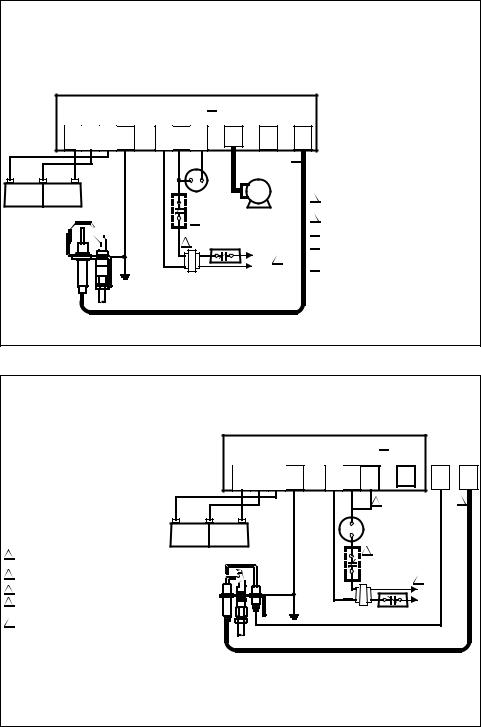
A MUST BE APPROVED SAFETY-CIRCUIT WIRING. A COMBINATION scREw, 114 INCH 0uicK CONNECT TERMINAL (3). POWERPILE OPERATOR COIL (INTERNAL WIRING). PILOTSTAT POWER UNIT COIL (INTERNAL WIRING). Fig. 4 -Typical Powerpile system wiring diagram. 1. Install Powerpile thermostat, limit control (if re-
Honeywell S8610u3009 Intermittent Pilot Control Supplyhouse Com
Fig. 4- Typical wiring diagram for TC, TD zoned heating/cooling system.Your new Honeywell Chronotherm III Fuel Saver Thermostat is a precision instrument that's quality-built to give you many years of satisfactory service. Each day of the week can be programmed independently so that, regardless of your schedule, you'll save fuel while ...

Universal Gas Furnace Intermittent Pilot Control Installation Honeywell S8610u Youtube
Honeywell Rth221b Wiring. Honeywell thermostat wiring instructions for 4 & 5 wire applications. Learn how to wire basic thermostats and digital thermostats to operate heat and cooling. Apr 21, I purchased one of these Honeywell RTHB thermostats to try it out, but the instructions are pretty much useless and my wires coming out of.
Series 5 Ignition Control Instruction Manual Capable Controls
tm by Honeywell THR840DUK Digital Thermostat 15 Connect system wiring Connect wiring from your heating or cooling equipment to the thermostat as shown at left. See wiring diagrams on pages 15-17 for details. 1 Make sure electrical power is off. 2 Strip insulation to expose about 6 mm of bare wire. 3 Use a screwdriver to loosen terminal screw,
Series 5 Ignition Control Instruction Manual Capable Controls
Gas Control: Honeywell models VR8204 and VR8304 Operating Temperature: Minimum ambient temperature rating is -40°F (-40°C). Maximum ambient rating for S8600 used with 1.0A main valve is 175°F (79°C). Maximum ambient rating for S8610 and S8670 used with 2.0A main valve is 165°F (74°C). Relative humidity: 0% to 95% noncondensing PLANNING THE
69 0644 1 St9120u Universal Electronic Fan Timers Honeywell
Honeywell S8600 Wiring. Jump to Latest Follow 1 - 20 of 35 Posts. 1; 2; Next. 1 of 2 Go to page. Go. Last. B. bdp1999 · Registered. Joined May 2, 2012 · 26 Posts . Discussion Starter · #1 · May 2, 2012. I have a two wire setup going off of my boiler, but I just recently purchased a Filtrete 3M50 Thermostat. ...
2
May 22, 2019 · Honeywell S8600 Wiring Diagram. Malfunctions of the HONEYWELL SV "Smart Earlier models used a HONEYWELL SM spark to . TYPICAL WIRING SCHEMATIC – F manufactured by Honeywell, Robertshaw, Johnson. Controls A complete list of the specific Honeywell and other .. Check the wiring diagram provided on the. with troubleshooting charts and wiring ...
Help With Connecting Furnace Ignition Module Doityourself Com Community Forums
How To Wire PIR Motion Sensor Light SwitchCorrect Wiring probably saves an expensive PIR Sensor from an irrecoverable malfunction and annulment of any Warran...

How Can I Test A Honeywell Aquastat L8148e1265 Doityourself Com Community Forums
Page 11 Of Honeywell Water Pump S8600 User Guide Manualsonline Com

How Can I Test A Honeywell Aquastat L8148e1265 Doityourself Com Community Forums
2

77 Luxury Aquastat Relay Wiring Diagram Diagram Component Diagram Relay

Baso Direct Spark Gas Ignition Control Pdf Ignition System Thermostat
2

Installation Data Universal Ignition Module Replacement Uni Kit Pdf Free Download

S8610u Wiring Diagram Smart Car Diagrams Mifinder Co Lively Honeywell To For Honeywell S8610u Wiring Diagram Honeywell House Wiring Diagram
2
68 0135 S8610u Universal Intermittent Pilot Module Tradeline Ra832a

Home Improvement Honeywell S8610f Intermittent Pilot Module Control Board S8610f1008 Home Garden
Vr8304p4504 U

Honeywell Intermittent Pilot Module Control Board S8610m S8610h S8660k S8660j 159 95 Picclick
Honeywell S8610u3009 Canada Control Board Intermittent Pilot Control Canadian 1844 737 2787 Youtube
2
2
Troubleshooting Parts4heating Com
2

Home Wiring Diagram In India Sakuraaiman
Honeywell S8600 S8670 S8660 S8610 User Manual
0 Response to "43 honeywell s8600 wiring diagram"
Post a Comment