43 sip call flow diagram
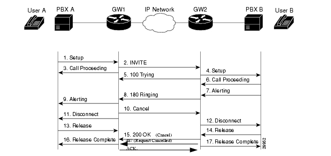
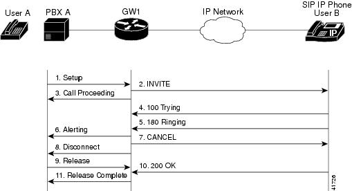
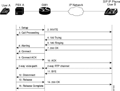
Aug 29, 2011 · Call flow between Gateway-to-Cisco SIP IP Phone Call—Successful Call Setup and Call Hold Below diagram illustrates a successful gateway-to-Cisco SIP IP phone call setup and call hold. In this scenario, the two end users are User A and User B. User A is located at PBX A. PBX A is connected to Gateway 1 (SIP Gateway) via a T1/E1. Session Initiation Protocol (SIP) Call Flow Examples with PASSporT Diversion and History-Info draft-barnes-stir-passport-div-hi-callflows-02. Abstract. This document focuses on use cases and call flows which include the History-Info header field and a SIP Identity header field with a PASSport with a "div" claim in cases of retargeting.
NG9-1-1 Call Flow Handout Roundtable April 2, 2012 Figure 1- Call Flow Diagram The Standard NG9-1-1 Network has the same Functional Elements (FEs) in each Data Centers for redundancy. The acronyms are explained in the text that follows. The blue boxes represent additional FEs with the i3 NENA Standard architecture and design.

Sip call flow diagram
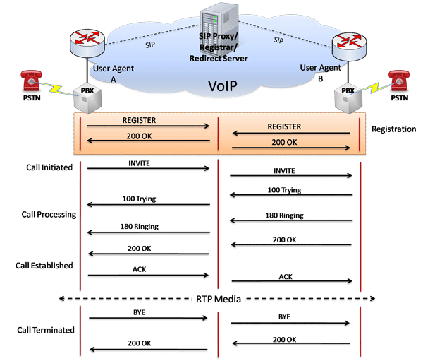
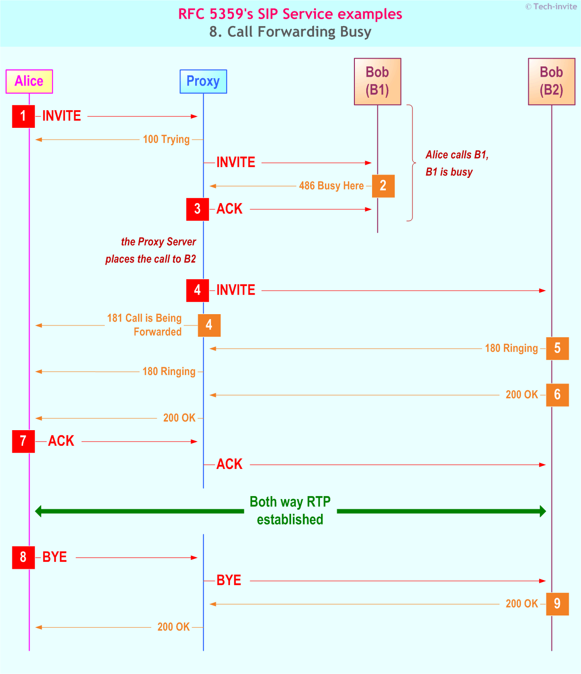
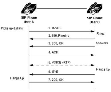
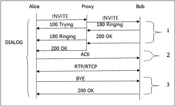
In the above basic call flow, three transactions are (marked as 1, 2, 3) available. The complete call (from INVITE to 200 OK) is known as a Dialog. SIP Trapezoid. How does a proxy help to connect one user with another? Let us find out with the help of the following diagram. The topology shown in the diagram is known as a SIP trapezoid. Refer to call flow diagrams for high level interworking scenarios. Web GUI Page. Dialogic > Profiles > SIP Profiles > SIP Profile (Not Default Profile) > New SIP To SS7 Interworking (RFC 3398) (Q.1912.5) Maximum Objects. 1 SIP To SS7 Interworking object Pane per SIP Profile (SGP) object pane Related Topics and Dependencies SS7 ISUP To SIP ... SIP is based on a request/response transaction model where each transaction consists of a request that invokes a particular method or function on the server and at least one response. Diagram of a request, acceptance, setup and termination of a call.
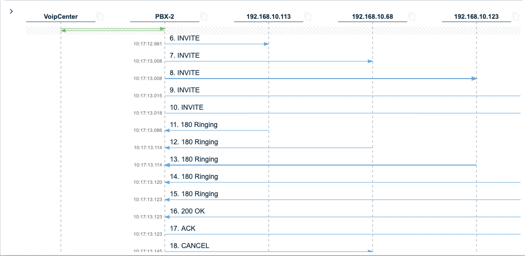
Sip call flow diagram. Creating SIP call flow sequence diagrams from network traces January 16, 2019 Whenever I am writing some sort of documentation of SIP call flows or call scenarios, I feel the need to add a SIP call flow sequence diagram to visualize the endpoints and servers involved, and their interaction with each other. SIP Call Flow. Basic SIP session setup involves a SIP UA client sending a request to the SIP URL of the called endpoint (UAS), inviting it to a session. If the UAC knows the IP address of the UAS, it can send the request. Otherwise, the UAC sends the request to a proxy or redirect server to locate the user. Have multiple people on a conference call; Run video calls; SIP trunks work as an intermediary between your business phone system and the Internet Telephony Service Provider (ITSP). See the diagram below showing how calls flow from a SIP phone (VoIP) in a business to the outside world—it's fascinating! With the diagram created and the collaboration stereotyped, you can place UML lifelines in the diagram. The lifelines represent the participants in the call flow and typically involve one or more User Agents (UA), Proxies, or generic SIP Servers.
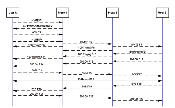
Call Flow Examples (using Wireshark) In the call flow examples that follow, Wireshark was used to analyze the PCAP data. To do this in Wireshark simply open the PCAP file and navigate to Telephony > VoIP Calls. Select the call that is of interest and press the Flow sequence button. This will then display the SIP call flow diagram for that call. The Oracle® Enterprise Session Border Controller can perform protocol translations for SIP and H.323 Fast Start, where media capabilities are sent with the Setup request for an H.323 session. This section's call flow diagrams show how SIP and H.323 messages flow between SIP and H.323 devices, with the Oracle® Enterprise Session Border Controller positioned between the two entities so it ... SIP Call Flow - Actual IMS Nodes - MO / MT Call Flow This is only Pictorial diagram of Whatever we discussed this now , This represents actual flow of Packets between various IMS Nodes We can clearly see SIP Invite Going from Originator to A Party P-CSCF to S-CSCF , Every Node Provides back Acknowledgement back to Previous Node by 100 ... SIP INVITE Call flow through two proxies. From the above image we can see that, User Agent "A" is calling User Agent "B". "A" will initiate a SIP session by sending "INVITE" request (M1) to the proxy server. The proxy server will challenge "A" by sending "407" response (M2). "A" will acknowledge it by sending "ACK ...
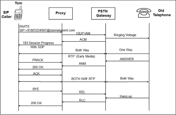
For more examples of SIP call flows and best practices. These examples show the SIP details with call flows that include SIP User Agents and Clients, SIP Proxy and Redirect Servers. Scenarios include SIP Registration and SIP session establishment. Call flow diagrams and message details are shown. Call flow: It's a flow diagram of SIP messages -- shows an ideal way how a media session carried over two endpoints. Its a must know thing and will be useful for your troubleshooting as well. Endpoint: Any device which is used to originate and terminate a media session. For example SIP phones, SIP clients running on PCs, webRTC running in ... Click the Flow Sequence button we can see the graph of this call with some details: SIP signaling flow between different UA. Direction, source and dest port of RTP stream. Codec of the RTP stream. 2) Filter one SIP call. In SIP protocol, we can use call-id, from-tag, to-tag to identify a call. SIP to SS7 ISUP Interworking Call Flow Diagram. Field Descriptions (ANSI - RFC 3398) Use the Call Flow diagram above for reference when reading descriptions below. 183 ISUP Mapping Procedure and 183 Mapping Condition. The table below displays the scenarios for both RFC 3398 and Q.1912.5. The first two columns display the settings as displayed ...
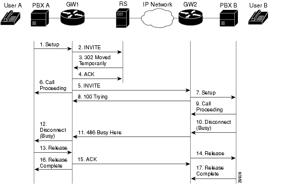
Appendix B SIP Call Flows Call Flow Scenarios for Successful Calls Call Setup and Hold Figure B-2 illustrates a successful phone-call setup and call hold. In this scenario, the two end users are User A and User B. User A is located at PBX A. PBX A is connected to Gateway 1 (SIP gateway) via a T1/E1. ...
Step 4. Select the required call and then clock Trace call. You must check the box for include SIP messages, as shown in the image, if you want to see SIP signalling and SDP messages. Step 5. You can view the entire call flow under the section Call flow diagram and to view logs related to any specific SIP message click on it. Step 6.
How SIP to SIP Call Flow Works. There are various forms of SIP call flows depending on the software involved—basic SIP to SIP, proxy servers, SIP Gateways, etc. Here we’ve focused on the basic SIP call flow: a direct call from one SIP user to another. Source. Without knowing the usual SIP requests and response codes, this diagram may be ...
This article describes Azure Communication Services call flow topologies. This is a great article to review if you're an enterprise customer integrating Communication Services within a network that you manage. ... Third-party SIP proxy servers. ... The direction of the arrows on the above diagram reflect the initiation direction of the ...
Detailed call flow is shown here, 3. Call flow: IP Phone to H.323 Voice Gateway with Gatekeeper . In this scenario, Phone A is registered to the CUCM. Phone B is connected to a carrier's CO switch. Below diagram illustrates this call setup between two IP phones registered to the same CUCM. A call is placed from Phone A (555-2001) to Phone B ...
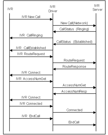
Ladder Diagram. The call flow changes depend on where the call originates and reaches to ICM. It also depends on the signalling protocol used for the call. ... SIP - CUCM sends the call to ICM and ...
The call flow diagrams were generated using EventStudio System Designer. SIP and H.323 Call Flow Diagrams. SIP to PSTN Sequence Diagram. In this scenario, Alice is a SIP phone or other SIP-enabled device. Bob is reachable via the PSTN at global telephone number. Alice places a call to Bob through a Proxy Server (Proxy 1) and a Network Gateway ...
The SG defines the Call Routing Table to use for processing the call, sba: SIP to ISDN in this case. The Call Routing Table contains a list of call routing entries. Those call route entries define which Transformation Table (sba:Lync to SIP Reg) to use in manipulating the call's numbers, names, etc. If the transformation is valid, the call is ...
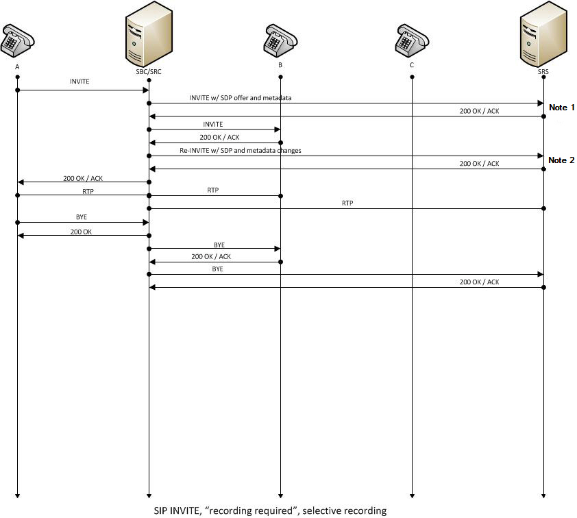
The following diagrams illustrate this scenario. Before Consultation. The initial call when the customer (D1) is talking to the agent (D2). During Consultation. When the agent initiates a consultation to the supervisor (D3), the existing SIP dialog is retained and so is the Recording Session.
Call flows in various topologies. Illustrates the use of call flows in various topologies. For each topology, the section enumerates all supported flows and illustrates how these flows are used in several use cases. For each use case, it describes the sequence and selection of flows using a flow diagram. Teams with Express Route optimization ...
RFC 3665 SIP Basic Call Flow Examples December 2003 These call flows are based on the current version 2.0 of SIP in RFC 3261 [] with SDP usage described in RFC 3264 [].Other RFCs also comprise the SIP standard but are not used in this set of basic call flows. Call flow examples of SIP interworking with the PSTN through gateways are contained in a companion document, RFC 3666 [].
SIP is based on a request/response transaction model where each transaction consists of a request that invokes a particular method or function on the server and at least one response. Diagram of a request, acceptance, setup and termination of a call.
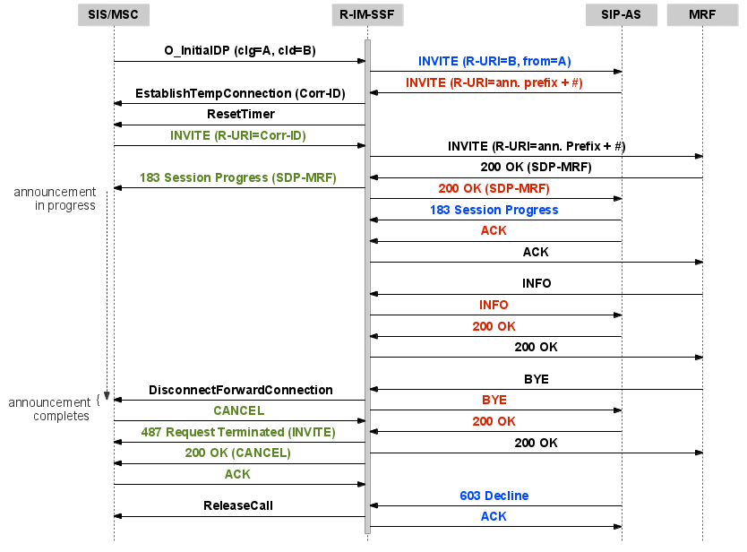
Refer to call flow diagrams for high level interworking scenarios. Web GUI Page. Dialogic > Profiles > SIP Profiles > SIP Profile (Not Default Profile) > New SIP To SS7 Interworking (RFC 3398) (Q.1912.5) Maximum Objects. 1 SIP To SS7 Interworking object Pane per SIP Profile (SGP) object pane Related Topics and Dependencies SS7 ISUP To SIP ...
In the above basic call flow, three transactions are (marked as 1, 2, 3) available. The complete call (from INVITE to 200 OK) is known as a Dialog. SIP Trapezoid. How does a proxy help to connect one user with another? Let us find out with the help of the following diagram. The topology shown in the diagram is known as a SIP trapezoid.















0 Response to "43 sip call flow diagram"
Post a Comment