43 stress strain diagram for steel
When steel is curved, it is important to keep the stress-strain curve ratio for mild steel in mind. Below is a stress-strain graph that reviews the properties of steel in detail. If tensile force is applied to a steel bar, it will have some elongation. If the force is small enough, the ratio of the stress and strain will remain proportional. Nov 04, 2016 · In this diagram stresses are plotted along the vertical axis and as a result of these stresses corresponding strains are plotted along the horizontal axis. The stress strain diagram for mild steel. The graph of these quantities with the stress σ along the y axis and the strain ε along the x axis is called the stress strain diagram. The stress strain diagram for a steel alloy having an of original diameter of 05 in. Yield strength stress for mild steel.
A schematic diagram for the stress-strain curve of low carbon steel at room temperature is shown in figure 1. There are several stages showing different behaviors, which suggests different mechanical properties. To clarify, materials can miss one or more stages shown in figure 1, or have totally different stages.
Stress strain diagram for steel
Stress strain curve is a behavior of material when it is subjected to load. In this diagram stresses are plotted along the vertical axis and as a result of these stresses, corresponding strains are plotted along the horizontal axis. As shown below in the stress strain curve. From the diagram one can see the different mark points on the curve. The stress-strain relationship of a material usually can be obtained from tensile or compression test on a specimen of the material. Figure 1.9 shows the stress-strain behavior which indicates how the material deforms on the application of load. The normal stress for the material is computed by dividing the load (P) by the original cross ... Introduction to engineering stress-strain diagrams for metals. Made by faculty at the University of Colorado Boulder Department of Chemical and Biological En...
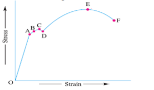
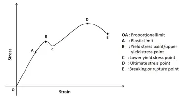
Stress strain diagram for steel. This is the maximum stress a material can bear. Value of stress correspond to peak point on stress strain curve for mild steel is the ultimate stress. It is denoted by point E in diagram. Breaking stress. Point on the stress strain curve where material fails, is known as breaking point. Stress correspond to this point is known as breaking ... The stress-strain diagram for different material is different. It may vary due to the temperature and loading condition of the material. How to Draw Stress-Strain Curve or Diagram. A tensile test is done on the material for drawing the stress strain curve. A specimen of specific dimension is taken generally a circular rod. The entire process is plotted in a curve and the same is known as stress-strain curve of steel. Stress-strain curve of materials. Stress strain curve of steel, aluminum, cast iron, elastomers etc., are described. Stress Strain Curve for Steel. Curve. Refer to below diagram for stress strain curve of steel. t ⇒ Tangent Modulus - Slope of the stress-strain curve above the proportional limit. There is no single value for the tangent modulus; it varies with strain. G ⇒ Shear Modulus - Slope of the initial linear portion of the shear stress-strain diagram. G (Steel) ≈ 12 x 106 psi G (Aluminum) ≈ 4 x 10⁶ psi
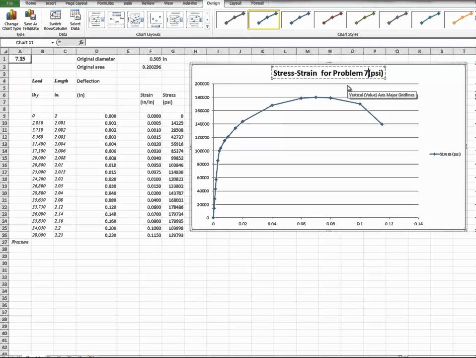
Stress Strain Diagram For mild Steel and Concrete and copper. Welcome to howtocivil.From This article, you will find three stress-strain diagrams for Mild Steel, Concrete, and Copper.. The Stress Strain Diagram For mild Steel Allowable stresses are 80MPa and 140MPa in copper and steel, respectively; α = 18 × 10–6 K–1 for copper and 12 ×10–6K–1for steel. 5. A 3.5m long steel column of cross-sectional area 5000mm2 is subjected to a load of 1.6 MN. Determine the safety factor for the column, if the yield stress of steel is 550MPa. Ramberg-Osgood Equation The stress-strain curve is approximated using the Ramberg-Osgood equation, which calculates the total strain (elastic and plastic) as a function of stress: . where σ is the value of stress, E is the elastic modulus of the material, S ty is the tensile yield strength of the material, and n is the strain hardening exponent of the material which can be calculated based on ... STRESS-STRAIN DIAGRAM: The mechanical properties of a material are determined in the laboratory by performing test on the small specimens of the material. Most common material test is the Tension Test. In this test, loads are measured on the main dial of the machine while the elongations are measured with the help of extensometers. It consists of a cylindrical specimen having a diameter of 0.5 ...
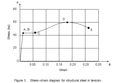
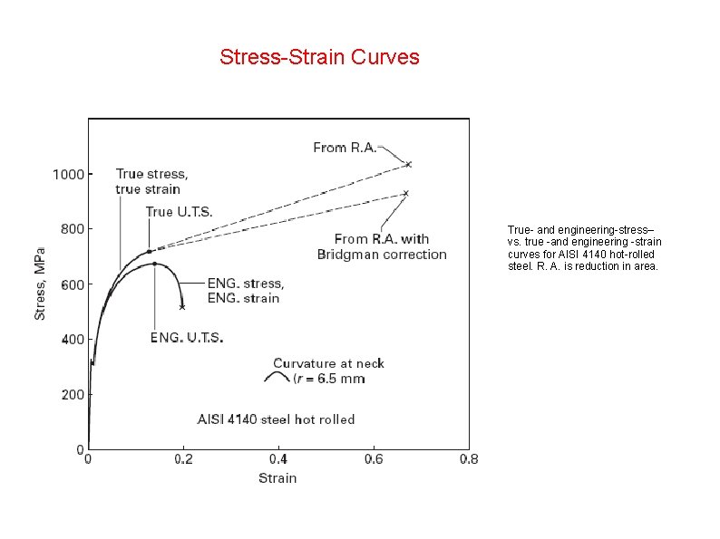
The stress-strain diagram differs in form for various materials. The diagram shown below is that for a medium-carbon structural steel. Metallic engineering materials are classified as either ductile or brittle materials. A ductile material is one having relatively large tensile strains up to the point of rupture like structural steel and aluminum, whereas brittle materials has a relatively small strain up to the point of rupture like cast iron and concrete. Stress Strain Diagram brittle Material . The diagram below shows Stress strain graph for a brittle and a ductile material. A typical brittle material is Cast Iron. Steels become increasingly brittle as the carbon content increases. Brittle fractures are generally clean and the ends of the test piece are sqaure and mate together. True Stress and Strain Developing a Stress–Strain Diagram Stress–Strain for Steel The first material we will discuss is: structural steel A stress–strain diagram for a typical structural steel in tension is shown: Elastic Plastic Strain Hardening Necking Fracture Ultimate Stress Yield Stress s Stress–Strain for Steel 0.05 0.10 0.15 0.20 0.25 20 40 60 Strain CIVL 1101 Introduction to Mechanics of Materials - Part 2 1/5 Alloy steel stress-strain diagram. The engineering tension test is widely used to provide basic design information on the strength of materials and as an acceptance test for the specification of materials. In the tension test a specimen is subjected to a continually increasing uniaxial tensile force while simultaneous observations are made of ...
Stress Strain Curve For Steel And Resulting Points Of Interest Youtube
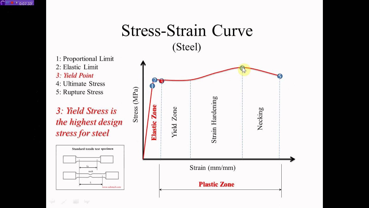
Between points B and C on the stress-strain diagram there is a transition from elastic stretch to plastic flow. The transition occurs because bulk metals are typically composed of many randomly-oriented crystal grains. As you may know, metal crystal grains flow by application of shear stress.

Stress Strain Characteristics Of Steels Protocol
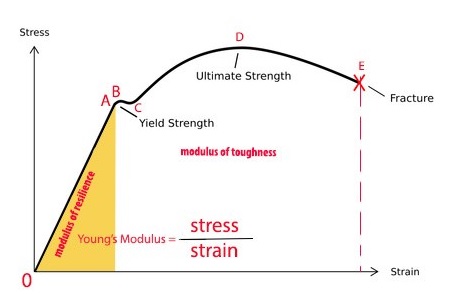
From stress-strain diagram: Proportional Limit = 246.20 MPa Modulus of Elasticity E = slope of stress-strain diagram within proportional limi E = 246.20/.0012 = 205 166.67 MPa = 205.2 GPa Yield Point = 270.24 MPa Ultimate Strength = 441.74 MPa Rupture Strength = 399.51 MPa

Stress Strain Diagram Of Mild Steel Mechanical Engineering Video Edurev
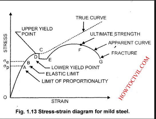
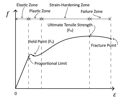
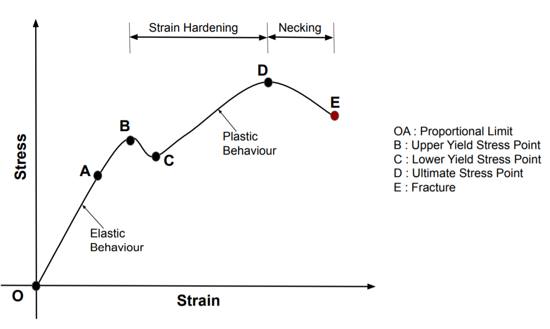
Proportional limit. It is the limit at which material follows Hook's law and represents the maximum value of stress at which the stress-strain diagram is linear and within this limit, the ratio of stress to strain gives a proportional constant called Young's modulus. The line OA on a stress-strain diagram shows a proportional limit.

Stress Strain Curve For Mild Steel Civil Engineering Notes
Stress-Strain Diagrams of Steel. version 1.0.1 (1.9 KB) by Ayad Al-Rumaithi. Calculates stress value of steel given strain and material properties . 5.0 (1) 175 Downloads. Updated 06 Jun 2019. View Version History. × Version History. Download. 6 Jun 2019 ...
What Is The Stress Strain Curve For Mild Steel Aluminium And Cast Iron Quora
2-4 Stress-Strain Diagrams STRESS-STRAIN DIAGRAMS σ ε σ ε P P Low-carbon steel Aluminum Alloy True stess-strain diagram (ductile material) ... Determine the largest allowable temperature increase if the stress in the steel is not to exceed 55 MPa. Units: mm. E (brass)= 105 GPa, α= 20.9E-6/°C E (steel)= 200 GPa, α= 11.7E-6/°C 500 Column ...
1
Knowing the original cross-sectional area and length of the specimen, the normal stress σ and the strain ε can be obtained. The graph of these quantities with the stress σ along the y-axis and the strain ε along the x-axis is called the stress-strain diagram. The stress - strain diagram differs in form for various materials.

3 1 3 Just For You
Stress-strain Curve of Steel Bars . When the steel specimen is subjected to load, it goes through several stages such as elastic stage, yield point, and fracture. The important stages of the stress-strain diagram are presented below: Fig. 1: Stress-strain Curve. Limit of Proportionality.

Pin On Ahmed
Typical graphical results for the complete stress-strain curves are shown in Fig. 5. Note the very large differences in the stress-strain characteristic, range from a very mild but ductile A36 steel to a very strong but non-ductile C1018. Note that both are conventionally called steel, but their performance is markedly different.

Stress Strain Curve An Overview Sciencedirect Topics
Download scientific diagram | Stress-strain curve of S220 steel rebar. from publication: Properties of Reinforced Concrete Steel Rebars Exposed to High Temperatures | The deterioration of the ...

Stress Strain Curve For Mild Steel Engineering Stress And True Stress Youtube
no longer linearly proportional to strain. On stress strain curve, proportional limit is shown by P. It is denoted by σPL. For annealed mild steel the limit of proportionality occurs at 230 MPa . The above graph shows that the length of graph up to proportional limit (P) is a straight line which means that up to proportional limit stress is linearly proportional to strain. • Elastic Limit (σEL)

File Stress V Strain A36 2 Svg Wikimedia Commons
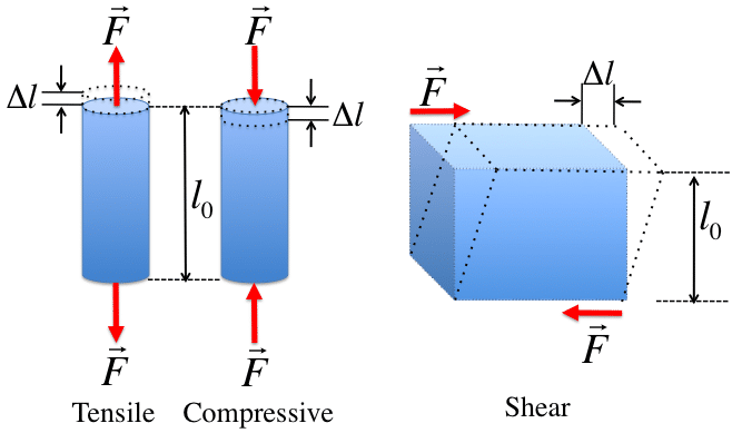
Stress and Strain Definition: In engineering, stress has been defined is: when an external force applied to the object (made of an elastic material), they produce a change in shape and size of the object. Stress is defined as, the deformation force per unit area of the body or material. Stress is the internal force (per unit area) associated ...
Civl 1101
The stress-strain curve is the most reliable and complete source for the evaluation of mechanical properties of any fibre. The stress-strain curve is produced by plotting the applied stress on the fibre axis and the elongation produced due it. The stress-strain curve of a model fibre is shown in Fig. 3.1. Different types of fibre produce ...

Stress Strain Curves Of As Rolled Steel And Heat Treated Specimens A 1 Download Scientific Diagram
Introduction to engineering stress-strain diagrams for metals. Made by faculty at the University of Colorado Boulder Department of Chemical and Biological En...
Chapter 3 Plasticity Tests For Mechanical Strength Of
The stress-strain relationship of a material usually can be obtained from tensile or compression test on a specimen of the material. Figure 1.9 shows the stress-strain behavior which indicates how the material deforms on the application of load. The normal stress for the material is computed by dividing the load (P) by the original cross ...

3104 Steel Stress Strain Curve Evocd
Stress strain curve is a behavior of material when it is subjected to load. In this diagram stresses are plotted along the vertical axis and as a result of these stresses, corresponding strains are plotted along the horizontal axis. As shown below in the stress strain curve. From the diagram one can see the different mark points on the curve.
Stress Strain Diagram For Mild Steel And Concrete And Copper

Roymech Stress Strain Diagram
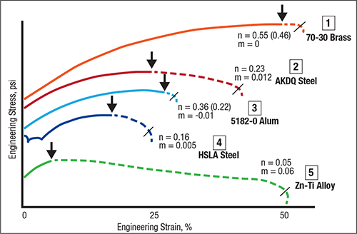
Stress Strain Curves Give Visual Clues About Formability Metalforming Magazine Article

Pdf Predictions Of Stress Strain Curve And Fatigue Life For Aisi 316 Stainless Steel In Cyclic Straining Semantic Scholar
Stress Strain Curve For Mild Steel With Defination Of Stress And Strain
Stress Strain Relationship Fundamentals Knowledgebase Safas

Stress Strain Curve Wikipedia

Gate Ese Stress Strain Curve For Mild Steel In Compression In Hindi Offered By Unacademy
Exploring The Stress Strain Curve For Mild Steel The Chicago Curve

Stress Strain And The Stress Strain Curve Materials Science Engineering
Explain With Neat Sketch The Stress Strain Diagram For Ductile Material Mechanical Engg Diploma Simple Notes Solved Papers And Videos

Stress Strain Curve For Mild Steel With Defination Of Stress And Strain

Engineering Stress Strain Curve Part One Total Materia Article

Figure 01 Steel Stress Strain Diagram Source 1

Description Of Stress Strain Curves For Stainless Steel Alloys Sciencedirect
Steel Stress Strain Curve Nazeer A Khan Youtube
Stress Strain Curve Strength Of Materials Smlease Design
Stress Strain Diagram For Mild Steel And Concrete And Copper

6 Stress Strain Graph For Mild Steel Youtube
What Is The Stress Strain Curve For Mild Steel Aluminium And Cast Iron Quora

Tensile Stress Strain Diagram Of Different Steels A Engineering Download Scientific Diagram

Stress Strain Diagram Showing The Tensile Properties Of Heat Treated Download Scientific Diagram
2
1

Engineering Tensile Stress Strain Diagrams
Stress Strain Curve Relationship Diagram And Explanation Mechanical Booster

Sketch The Standard Stress Strain Curve For Mild Steel And Tor Steel Bar Under Axial Tension And Show Important Points On It

Propagating Stress Strain Curve Variability In Multi Material Problems Temperature Dependent Material Tests To Plasticity Models To Structural Failure Predictions Intechopen
0 Response to "43 stress strain diagram for steel"
Post a Comment