44 line side tap solar diagram
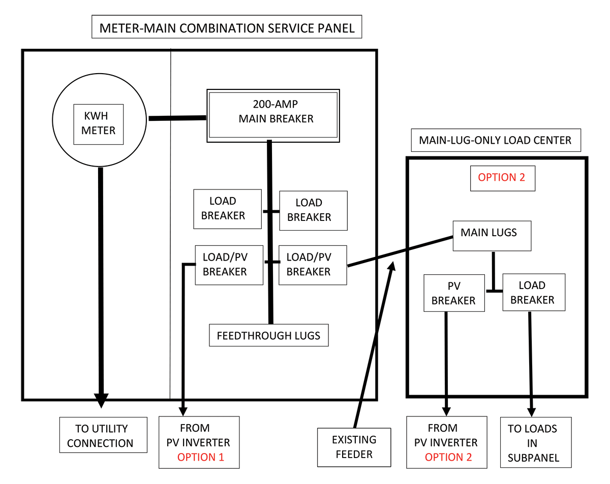
The alternative is a "LINE OR SUPPLY-SIDE" connection made BEFORE the main breaker. load-side-connection-diagram-for-pv-solar-systems. Aug 07, 2016 · The disconnect by the gas pedal is for the starter battery. Like you found out though, even with that disconnected the Aux battery is still attached to its side of the isolator circuit. When you are looking at the auxiliary connector, the black cable is the Auxiliary battery side, the red cable is the isolator/starter side.
Net Energy Metering Solar and Wind Generating Facility 10 kW or < Interconnection Agreement (Form 14-923) OR b) ... match the Single Line Diagram (SLD). Single Line Diagram: ... NEM application with a "Line-Side Tap" or point of connection is done between the main breaker and the service meter.
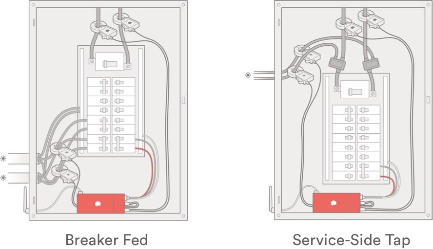
Line side tap solar diagram
Prior to 2011 your load side tap option was not addressed by the code. 240.21(B) also applies to taps. In your diagram you have a tap. But, by the way, if you just add a backfed breaker to a panelboard on the load side of the service disconnecting means, then it is a load side connection, but it is probably not a tap. DC Combiner Panel 3 ###A, ###VDC DC Combiner Panel 2 ###A, ###VDC DC Combiner Panel 1 ###A, ###VDC ##A XYZ Co. Model A Inverter ##kWAC, ###VAC AC Disconnect (if needed for Line Side Tap) Commercial Services—Cold Sequence rules apply Residential Services—Hot Sequence rules apply Production meter must be protected to 10,000 A fault current 3rd Party/Customer owned PV Production Meter (Optional - Not Required by Utility) Drawing Revised 9/25/14
Line side tap solar diagram. Our online solar software allows you to generate a single-line diagram of your residential PV design, along with a cover page, site plan, placards, attachment plan, attachment detail, fire safety plan, code-validated electrical calculations, and equipment data sheets. Connection Diagram. There's one main diagram here that needs explaining and it's the system layout. Starting from the left solar panel connectors, we designate positive and negative as connections one and two from PNL which connects straight to the source pin of our mosfet; the IRF9540N. Documentation is submitted during Step 2 of the Standard NEM Portal (select Line Side Tap) Once approved, customer must enter into a Special Facilities Agreement with PG&E and submit a one-time payment estimated at $1,047. This payment amount is for the GMA, the installation of the GMA, and any future maintenance or replacement that may be ... A transformer is a passive component that transfers electrical energy from one electrical circuit to another circuit, or multiple circuits.A varying current in any one coil of the transformer produces a varying magnetic flux in the transformer's core, which induces a varying electromotive force across any other coils wound around the same core. . Electrical energy can be transferred between ...
7.5 Is the Manufacturer's approval for load side tap or UL (or other NRTL) field evaluation performed? 7.6 For solar ready panels, is the appropriate tap model used in accordance with the panel manufacturer? 7.7 For solar ready panels, is the PV Source breaker sized according to the manufacturer's specifications? 7. Residential "solar ready" service panels designed with an alternative energy (customer generation) interconnection circuit breaker on the line side of the main breaker is allowable. "Solar ready" panels must be EUSERC approved and have factory installed labels showing location and ratings of the generation source 8. The LST2 diagram on the last page provides a partial detail of the tap connection. The position of the junction box will vary depending on the panel configuration and if the service is from overhead or underground to the meter. Line Side Tap 3 (LST3) - Line Side Tap connection installed to the bus between the meter and service main breaker. The line-side tap is technically an extension of the service conductors since there is no overcurrent protection other than that provided in the PV system disconnecting means. In the 2017 NEC, the rules have been reversed. Now, If the PV system is connected to the supply side of the service disconnecting means as permitted in 230.82(6), the PV ...
Installing clean energy technologies like rooftop solar and batteries at your home or business are good for the environment and can reduce your energy bill. It’s also a big decision. ... Typical Commercial Diagram (Line Side) ... 400A Typical Residential Diagram for Load Side Tap . That means you can't use any inverter higher than 3800 watts without getting a main panel upgrade or a "line side tap". The highest inverter output current acceptable for 20-amp breakers would be 16 amps, since 16 X 1.25 equal 20. Apr 26, 2021 · Solar power systems vary widely in their power producing capabilities and complexity. But I wanted to sketch a simple basic solar power system diagram that shows the building blocks. Regardless of a given system’s capacities and specifications, there’s a common thread among most of them: The basic building blocks of its major components. 1. One Line Diagram: Back-fed Breaker. Interconnection Only and REC Purchase Programs. Modules: 8 x 300 W = 2.4 kWdc. Inverter(s): 1 x 2000 W = 2.0 kWac. Storage (if applicable) : kWac. 505 Camino de Solar. Albuquerque, NM 87111. Solar panels. Manufacturer. Model number. Inverter. Manufacturer. Model number. Output Voltage. Utility Accessible . AC ...
LINE. G. G. N. SUPPLY SIDE TAP. REF NEC 230.82(6),. 705.12(A) FOR. SUPPLY SIDE TAP ... SILFAB SOLAR SIL-320 BL MODULES ... ELECTRICAL LINE DIAGRAM.1 page
One Line Diagram Example Line Side Tap **A line side tap CANNOT be contained in the billing meter** The purpose of this sample one-line diagram is show a utility line side tap. This occurs when the PV system is not wired into a back fed breaker within the house main service panel. Customer Generation Disconnect (CGD) REC Meter House Main ...
Option #3: Line Side Tap. An increasingly common solution is known as a Line Side tap, a.k.a. Supply Side tap. This work is usually done by a licensed electrician. The main breaker box is completely bypassed, and a fused AC Disconnect is used to connect the inverter to the grid between the utility meter and the main breaker box. This removes ...
supply side tap n ac disconnect: 60a fused, (2) 40a fuses, 240v nema 3r, ul listed, (if required by utility) supply side tap connection option (e)main breaker to house 240v, 200a/2p (v.i.f) (e)main service panel, 200a rated, 240v (shall be field verified) g bond #6 awg cu to new or existing ground rod (3)#6 thwn-2 in 3/4" conduit comply with ...
For Solar And/Or Wind Electric Generating Facilities Of 30 Kilowatts Or Less . Please complete this agreement in its entirety . Automated Document, Preliminary Statement, Part A. Page 4 of 6 Form 79-1151B-02 Advice 6270-E July 2021. E. Basic Single-Line Diagram (SLD) for Solar Projects (check one):
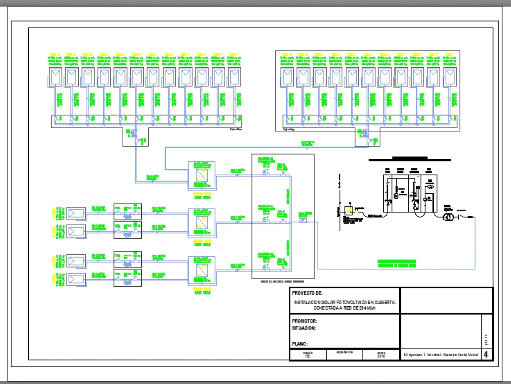
A solar one line diagram (also known as a single line diagram) is an electrical drawing used to design a solar PV installation. A one-page document, it details the main components within the system and uses single lines to show how they are connected. The diagram also includes a summary of the wiring and electrical calculations.
He needs batteres to supply the 1500w loads for 12hours at night. Basically that is 1500w * 12 = 18000wh. dividing by 50% depth of discharge as you choose flooded, that is 18000/0.5=36000wh or divde by 0.8 if for AGM batteries, that is 18000/0.8 = 22500wh.
May 27, 2015 · The diagram below shows the basic components of that system, and how the various wires are connected: Starting at the bottom left of the diagram, you can see the thick red line which represents the existing power cable for the geyser. This should be disconnected from the geyser and re-routed to the controller.
This panel design constitutes a line-side tap. A separate set of busbars, rated at 60 amps, is supplied for connecting to an inverter with a set of breakers. That set of busbars is connected directly to the load side of the meter socket before the main disconnect, bypassing the main busbars altogether.
• Section 5 - Clarified requirements for line side taps • Section 5 - Remote Control Switch-Generation requirements ... 5.2 Single Line Diagram ... solar thermal, photovoltaic, wind, geothermal, fuelcells using renewable fuels, small hydroelectric generation, ...
uses a line-side tap to connect the inverter input when backfeeding via the main panel is not feasible or in compliance. This configuration is acceptable for use with most utility services. 30A 30A 30A 30A Power Conversion PWRcellTM Inverter Generac PowerCore Router Ethernet (CAT5) 50A AC Grid Main Distribution Panel M Protected Loads Panel AC ...
Line-side tap connection: This method requires that the wires from the inverter are connected to the service wires on the line side of the circuit breaker. This connection is very rarely allowed for residential systems but is increasingly common in commercial systems.

Renewable Energy Systems Based On Micro Hydro And Solar Photovoltaic For Rural Areas A Case Study In Yogyakarta Indonesia Sciencedirect
We recently installed solar on line side of ATS using external tap box and city approved the installation , inspected and passed. Now for the interconnection utility is giving us hard time. the Generator installed previously was not given permission to operate by POCO. so They advised us to...
Please refer to diagrams section for complete wire diagram Strain Reliefs must be used for all wires going in/out of the Sol- Ark 12K user area Ground and Neutral must be wired as shown above, or damage can occur. Conduit (or double insulated wire) must be used for the AC Wires going to and from the Sol -Ark.
inverter and involves a line-side tap and two transfer switches. The inverter output supports a loads panel that can also be transferred to the generator. This configuration is acceptable with most utility services. NOTE: In this configuration, the generator does not charge PWRcell batteries or parallel with the inverter. 30A 30A 30A 30A Power ...
certified (UL Listed) and this line side tap has been deemed ... The LST2 diagram on the last page provides a partial detail of the tap connection.4 pages
Oct 11, 2021 · Solar power transformer and cable connections (credit: bowerselec.co.uk) ... When the load-side voltage is low, tap connections below 100% of line voltage must be used to raise the load voltage. If the load-side voltage is high, tap connections above 100% of line voltage must be used to lower the load voltage.
ABC Solar Grid Tie Single Line Diagram Load Side Tap Solar Electric Grid Tie. SINGLE LINE DIAGRAM The Single Line Diagram is needed for construction and permitting. STEP 1: CHOOSE SOLAR PANEL Over the years we have installed solar panels made by SolarWorld, Sanyo, Mitsubishi, Sharp, LG Solar, Suniva, JA Solar, Hyundai, and Sunpower (from black ...
The purpose of this sample one-line diagram is show a utility line side tap. This occurs when the PV system is not wired into a back fed breaker within the ...
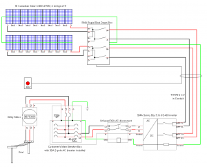
Note: this wiring diagram is simply an example. Diagrams may vary. SMA rapid shutdown box mounted under solar modules RS SMA rapid shutdown push button disconnect switch (mounted outside and adjacent to the service panel) #18 AWG THWN, 600V rated wire, ½" EMT
This is SLD (single line diagram) representation of single phase two winding transformer. ... It can vary the output voltage by changing the number of turns or using different tap points or by variable coupling. A Variac is the most common variable autotransformer. ... There are 3 windings on each side i.e. primary & secondary side. However the ...
A supply side tap is a connection that is made to the busbars or conductors on the line or utility side of the main service disconnect. The line side tap the simplest way of interconnection when installing a PV system that exceeds the 120% rule.
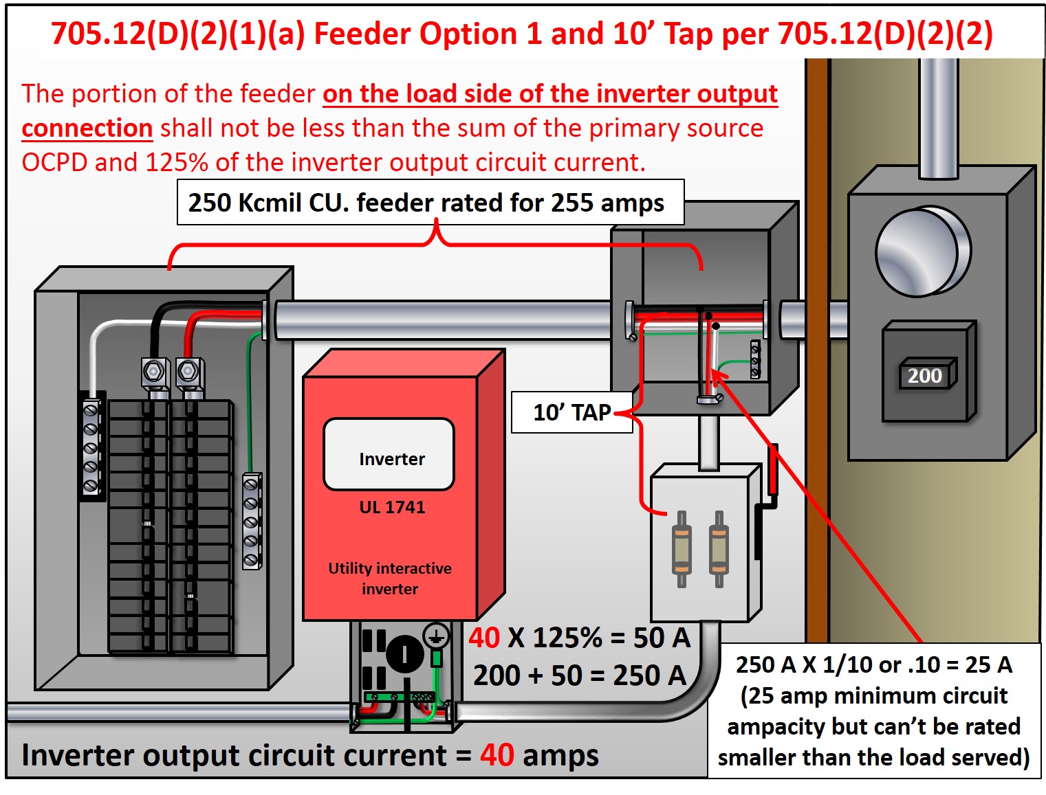
NEC Article 690.64(A) allows a Line‐Side AC connection to busbars, conductors, or lugs at any point between the customer's side of the utility meter, and the service disconnect. Many folks call this a "line‐side tap", which leads to confusion with the "10‐foot tap rule" and Article 240.21(B).
LST ARRAY DIAGRAM DRAWING NO. 1234 South Main Street Any City, Arizona 85123 Tel: 602-555-5555 ABC SOLAR COMPANY INC. 09-13-19 SAMPLE LOAD SIDE TAP ARRAY DRAWING This Sample Drawing is for illustration purposes only and is not to be used for design or construction. This drawing and its suitability for end use is not implied. The intent is to only
AC Disconnect (if needed for Line Side Tap) Commercial Services—Cold Sequence rules apply Residential Services—Hot Sequence rules apply Production meter must be protected to 10,000 A fault current 3rd Party/Customer owned PV Production Meter (Optional - Not Required by Utility) Drawing Revised 9/25/14
DC Combiner Panel 3 ###A, ###VDC DC Combiner Panel 2 ###A, ###VDC DC Combiner Panel 1 ###A, ###VDC ##A XYZ Co. Model A Inverter ##kWAC, ###VAC
Prior to 2011 your load side tap option was not addressed by the code. 240.21(B) also applies to taps. In your diagram you have a tap. But, by the way, if you just add a backfed breaker to a panelboard on the load side of the service disconnecting means, then it is a load side connection, but it is probably not a tap.






0 Response to "44 line side tap solar diagram"
Post a Comment