40 iron carbon phase diagram calculator
1) Equilibrium phase diagrams, Particle strengthening by precipitation and precipitation reactions 2) Kinetics of nucleation and growth 3) The iron-carbon system, phase transformations 4) Transformation rate effects and TTT diagrams, Microstructure and property changes in iron-carbon system Contents
Iron-carbon phase diagram, Pb-Sn diagram are the best examples of this category. 3. The temperature (in o C) of peritectic reaction in iron-carbon phase diagram is? a) 1539 b) 1493 c) 910 d) 1175. Answer: b Clarification: The invariant peritectic reaction (while cooling) in Fe-C phase diagram is given by:
9.52 Compute the mass fractions of proeutectoid ferrite and pearlite that form in an iron-carbon alloy containing 0.25 wt% C. Solution The mass fractions of proeutectoid ferrite and pearlite that form in a 0.25 wt% C iron-carbon alloy are considered in this problem.

Iron carbon phase diagram calculator
This sceencast is part four of our series about phase diagrams. This sceencast is focused on addressing issues students have with Iron-Iron Carbide (Steel) E...
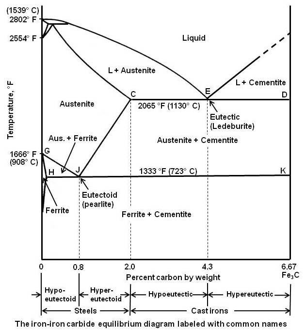
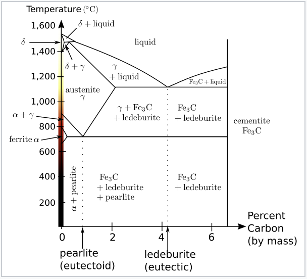
eutectic concentration of carbon is 4.3%. In practice only hypoeutectic alloys are used. These alloys (carbon content from 2.06% to 4.3%) are called cast iron. When temperature of an alloy from this range reaches (1130 ºC), it contains primary austenite crystals and some amount of the liquid phase. The latter decomposes by eutectic mechanism
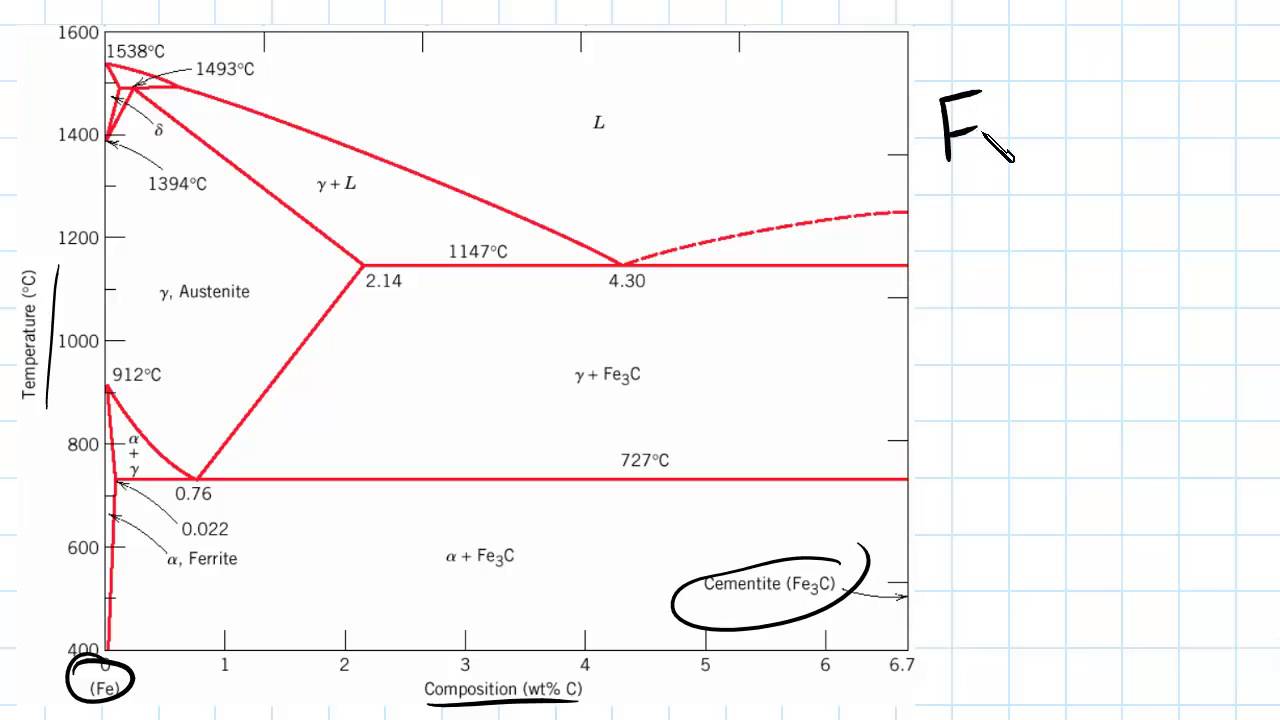
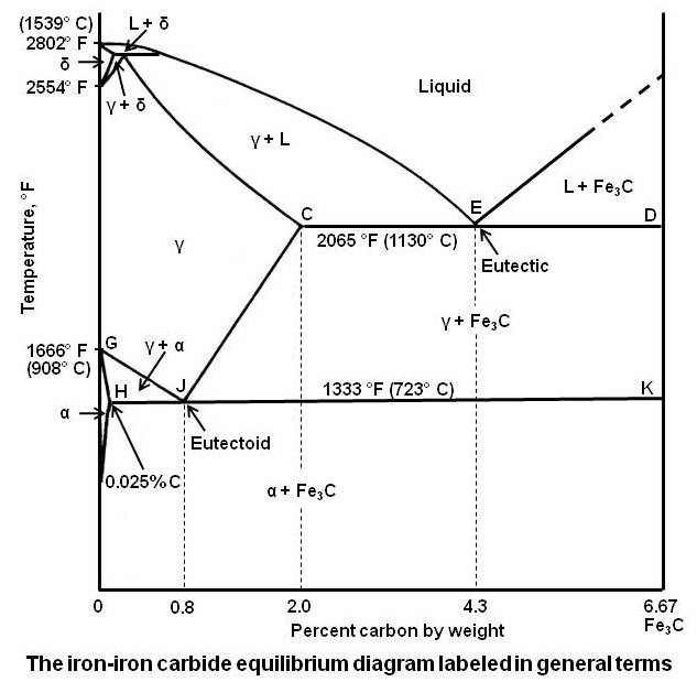
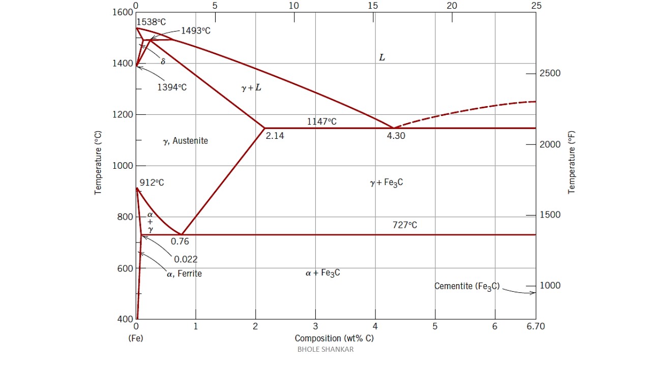
Iron-Iron Carbide Phase Diagram - Callister. Austenite is a polymorph of iron, in a face centred cubic (FCC) structure. Carbon is relatively soluble in this phase (up to 2% C at 1100°C). It is therefore found in mild carbon steel above the eutectoid temperature of 727°C. As it cools, the austenite transforms into the much less carbon soluble ...
Iron carbon phase diagram calculator.
the iron-carbon alloy system. A sample of the eutectoid composition is cooled from a single-phase region (γ) to a temperature (T) below the eutectoid temperature (T E). The following diagram shows a part of the iron-carbon phase diagram. Concentrations C 1, C 2, C 3, C 4 are various equilibrium ( stable as well as metastable ) concentrations ...
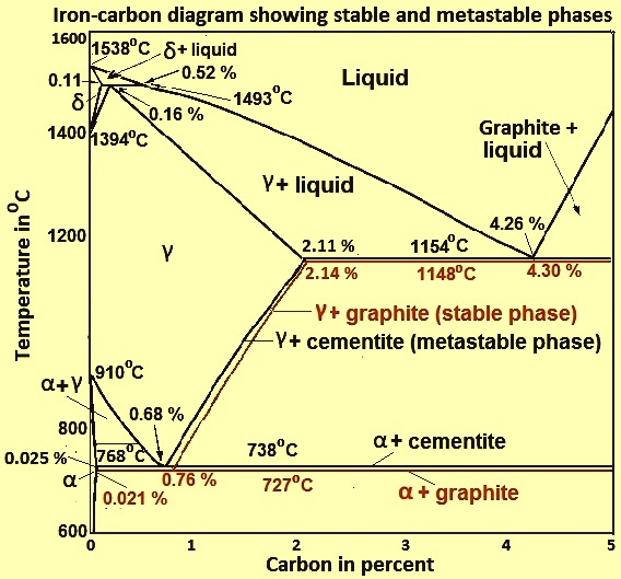
Iron-Cementite diagram is not a true equilibrium diagram, since equilibrium means no change of phase with time, however long it may be. Graphite is more stable form of carbon. Cementite is a metastable phase, which decomposes to graphite if given long periods of time. Graphitisation, however, rarely occurs in steels and may take years to form.
rule for the phase equilibrium diagrams calculations is to calculate the minimum free energy, G, ... The iron-carbon phase diagram plays the very ... standard iron-carbon the Chipman (1972) diagram is
Lecture 23-24 : Iron Carbon Phase diagram Questions: 1. FCC is a more close packed structure yet solubility of carbon in austenite which is FCC is higher than that in ferrite which is BCC. Why it is so? 2. Sketch the microstructure of 0.2% C steel. Calculate %Pearlite % cementite, % proeutectoid ferrite and % total ferrite. 3.
Iron-Carbon Phase Diagram • In their simplest form, steels are alloys of Iron (Fe) and Carbon (C). • The Fe-C phase diagram is a fairly complex one, but we will only consider the steel and cast iron part of the diagram, up to 6.67% Carbon. 3. Fe - C Equilibrium Diagram.
Carbon Steels and the Iron-Carbon Phase Diagram. Steels are alloys having elements of iron (Fe) and carbon (C). C gets dissolved in Fe during the production of steels. Pure Fe melts at a temperature of 1540 deg C, and at this temperature, C readily dissolves into the liquid iron, generating a liquid solution.
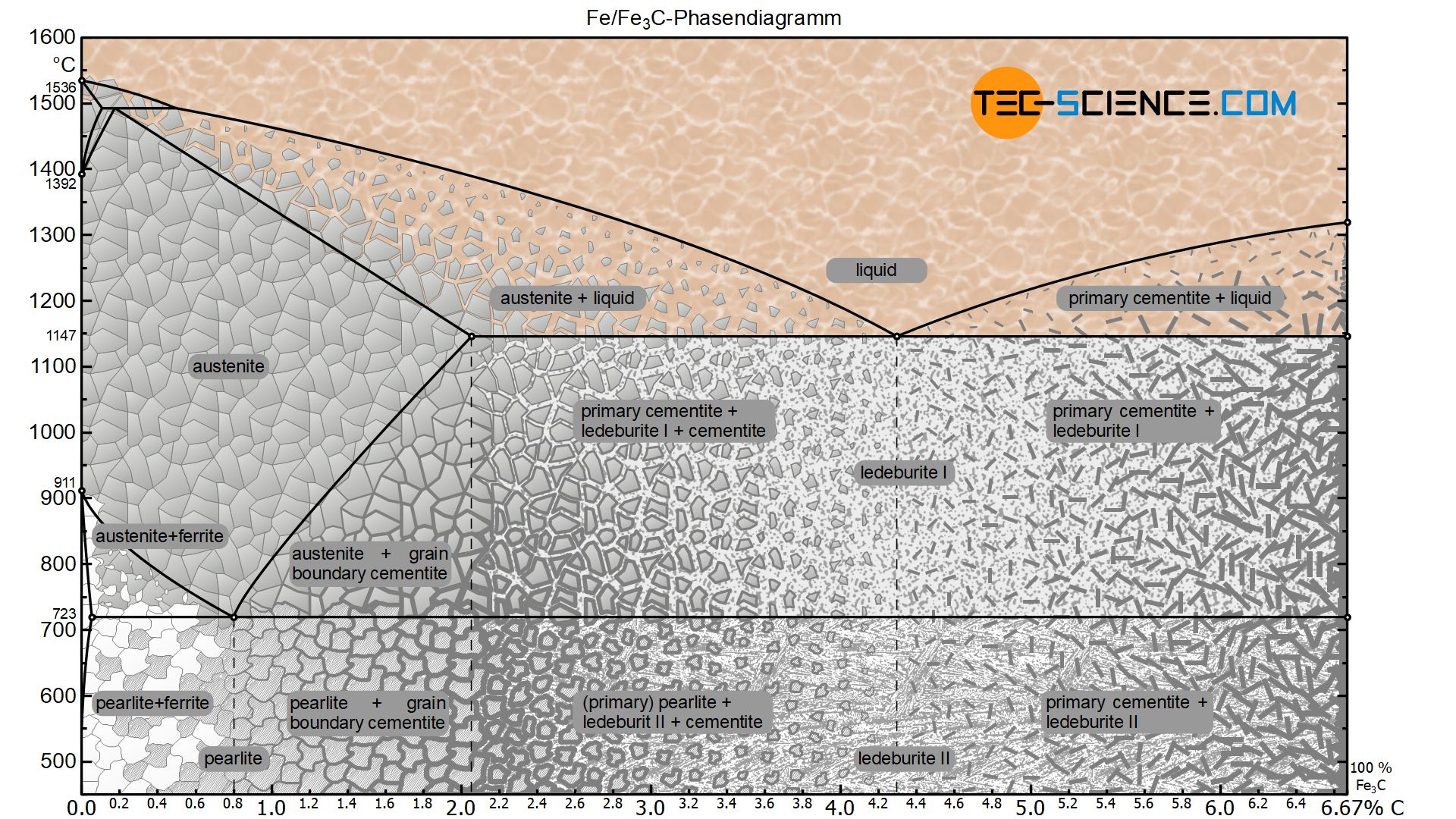
Figure: Complete iron-carbon phase diagram. In principle, however, the iron-carbon phase diagram of the metastable system ends at a carbon content of 6.67 %, since the microstructure consists of 100 % cementite. Chemically, the cementite consists of three iron atoms (each with an atomic mass of 56 u) and one carbon atom (with an atomic mass of ...
A Materials Science problem that calculates the proeutectoid ferrite,,eutectoid ferrite, and cementite weight fractions and masses of a 0.3% C steel as it co...
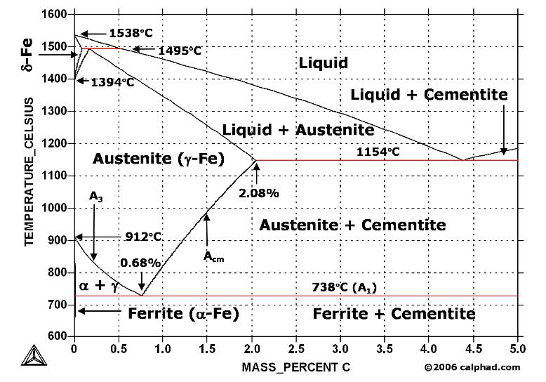
An iron-carbon alloy with 0.3 wt%C is heated up slowly from 1390°C to 1550°C. 1) Use information on the phase diagram to calculate the approximate values of the; Question: Below is a portion of the iron-carbon phase diagram on the iron side at high temperatures. y is a face-centered cubic (FCC) phase and d is a body-centered cubic (BCC) phase ...
Gray Iron • Gray iron was the original "cast iron", and is an iron alloy characterized by its relatively high carbon content (usually 2% to 4%). • When molten cast iron solidifies some of the carbon precipitates as graphite, forming tiny, irregular flakes within the crystal structure of the metal.
The Iron-Carbon Phase Diagram The phase diagrams are very important tools in the study of alloys for solutions of many practical problems in metallurgy. These diagrams define the regions of the stability of a phase which can exist in an alloy system under the condition of constant atmospheric pressure.
The iron-carbon system (steel and cast iron) MSE 2090: Introduction to Materials Science Chapter 9, ... Pressure-temperature phase diagram for carbon We can see graphite, diamond, liquid carbon on the phase ... and C calculate the compositions (wt. %) ...
4 iron-carbon phase diagram | download scientific diagram
The Iron-carbon phase or equilibrium diagram is an overall study of iron, carbon, and their alloys and how they act under the various equilibrium conditions. In this blog, we studied these aspects of the equilibrium diagram and also how phase transformation depends upon the temperature conditions.
Iron-iron carbide phase diagram example
The Fe-4.3% C alloy is called eutectic cast iron as it is the lowest melting alloy, which is single phase liquid (100%) of 4.3% carbon at the eutectic temperature, 1147°C just attained and undergoes eutectic reaction completely at this constant eutectic temperature to give a mixture of two different solids, namely austenite (c = 2.11 %) and ...
![Iron-carbon phase diagram [SubsTech]](https://www.substech.com/dokuwiki/lib/exe/fetch.php?w=&h=&cache=cache&media=iron-carbon_diagram.png)
Iron-carbon phase diagram [substech]
Hypereutectoid steel: has a carbon content greater than the eutectoid 8 Example: Phase Equilibria For a 99.6 wt% Fe-0.40 wt% C at a temperature just below the eutectoid, determine the following a) composition of Fe 3C and ferrite (α) b) the amount of carbide (cementite) in grams that forms per 100 g of steel

Iron carbon phase diagram
Iron-Carbon Phase Diagram with Detailed Explanation: If the percentage of the carbon is in the range of 0 to 2.11 % then it is called Steel and if the percentage of carbon is in the range of 2.11 to 6.67% then it is called Cast iron. As the carbon content increases, it produces more Iron-Carbide volume and that phase will exhibit high hardness.
Practical maintenance » blog archive » the iron-iron carbide ...
The Iron-Iron Carbide (Fe-Fe3C) Phase Diagram In their simplest form, steels are alloys of Iron (Fe) and Carbon (C). The Fe-C phase diagram is a fairly complex one, but we will only consider the steel part of the diagram, up to around 7% Carbon.

The iron carbon phase diagram
C Phase Diagram ¾α‐ferrite‐ ... How to calculate the relative amounts of proeutectoidphase ... carbon in iron. Due to the high lattice distortion, martensite has high residual stresses. The high lattice distortion induces high hardness and strength to the steel.
Introduction to iron carbon phase diagram | engineering materials
The iron-carbon phase diagram is widely used to understand the dif fe rent phase s of steel and cast iron. Both steel and cast iron are a mix of iron and carbon . Also, both alloys contain a small amount of trace elements.
![1: An excerpt of the Fe-C reaction phase diagram [68]. The ...](https://www.researchgate.net/profile/Claas-Hueter/publication/47758809/figure/fig20/AS:669574550790150@1536650421302/An-excerpt-of-the-Fe-C-reaction-phase-diagram-68-The-right-upper-circle-marks-the_Q320.jpg)
1: an excerpt of the fe-c reaction phase diagram [68]. the ...
Iron Carbon phase diagram. On this diagram, the carbon percentage is shown on the x-axis and temperature on the y-axis. This figure shows the Iron Carbon Equilibrium Diagram. In this diagram, the lines indicate the boundaries where the alloy changes its phase. The different phases or mixture of phases occur in different areas enclosed by these ...
Iron–iron carbide (fe–fe3c) phase diagram
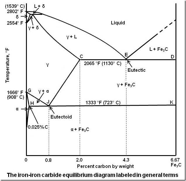
The Iron-Carbon Diagram: A map of the temperature at which different phase changes occur on very slow heating and cooling in relation to Carbon, is called Iron- Carbon Diagram. Iron- Carbon diagram shows - the type of alloys formed under very slow cooling, proper heat-treatment temperature and how the properties of steels and cast irons
Solved the phase diagram of iron – carbon: consider a 94 ...
Dr. Dmitri Kopeliovich Iron-carbon phase diagram describes the iron-carbon system of alloys containing up to 6.67% of carbon, discloses the phases compositions and their transformations occurring with the alloys during their cooling or heating.. Carbon content 6.67% corresponds to the fixed composition of the iron carbide Fe 3 C. . The diagram is presented in the picture:
Practical maintenance » blog archive » the iron-iron carbide ...
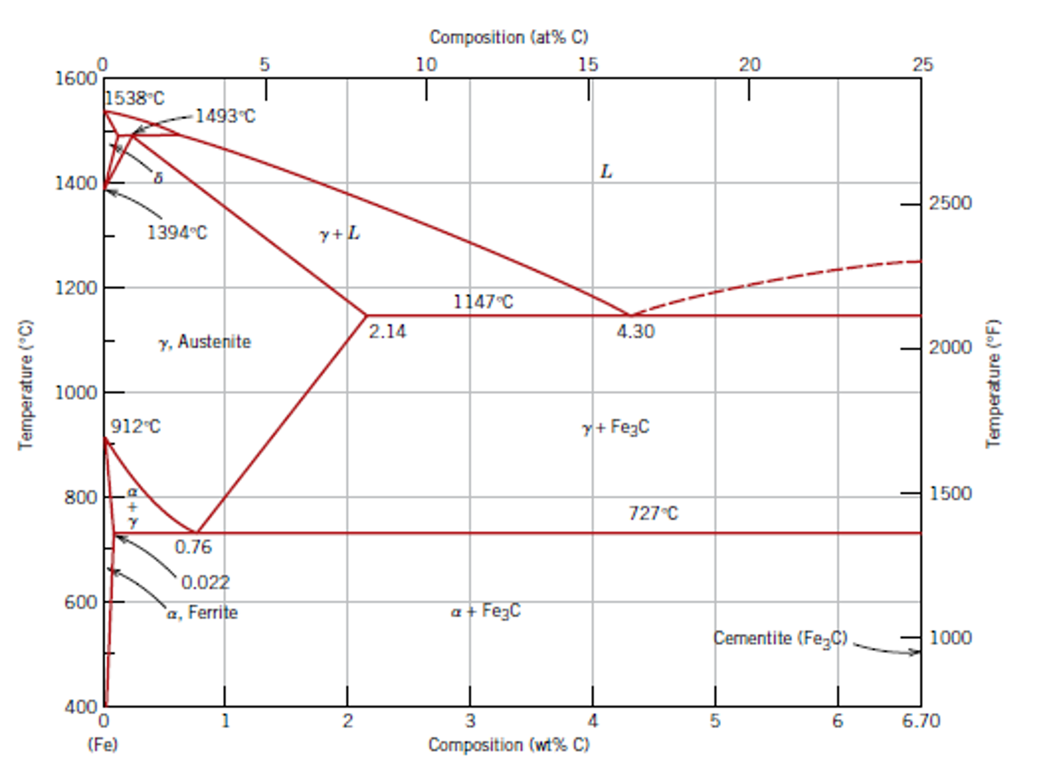
This iron carbon phase diagram is plotted with the carbon concentrations by weight on the X-axis and the temperature scale on the Y-axis. The carbon in iron is an interstitial impurity. The alloy may form a face centred cubic (FCC) lattice or a body centred cubic (BCC) lattice. It will form a solid solution with α, γ, and δ phases of iron.

The iron-carbon alloys and fe-c phase diagram - mechanicalbase

Iron-carbon phase diagram |
Determination of microstructure and phase fractions in steels ...
![Iron-Carbon Phase Diagram Explained [with Graphs]](https://fractory.com/wp-content/uploads/2020/03/Phase-diagram-of-steel-and-cast-iron.jpg)
Iron-carbon phase diagram explained [with graphs]

Solved by using the iron-carbon (fe-c) phase diagram | chegg.com

The iron carbon phase diagram

Muddiest point phase diagrams iv: fe-fe3c (steel ...

Please answer the following question regarding the iron-iron ...

Difference between steel and cast iron - engineering
Practical maintenance » blog archive » the iron-iron carbide ...

Fe-carbon phase diagram - ppt video online download

Iron-carbon phase diagram (note "perlite" is an alternative ...

Welding , hardfacing , cladding and cutting of metals ...
Phase diagram iron carbon | metallurgy for dummies
What is the difference between an iron carbon and a phase ...
The iron-carbon phase diagram – ispatguru

Iron-carbon (steel) phase diagram w/ pro-eutectoid step
7.4: iron and steel - chemistry libretexts
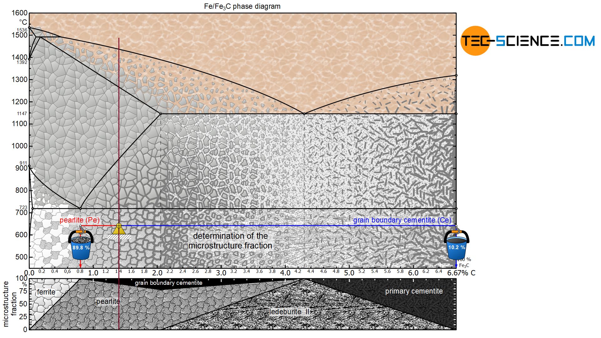
Determination of microstructure and phase fractions in steels ...

Iron carbon phase diagram - google search | metal working ...
Iron carbon phase diagram — steemit
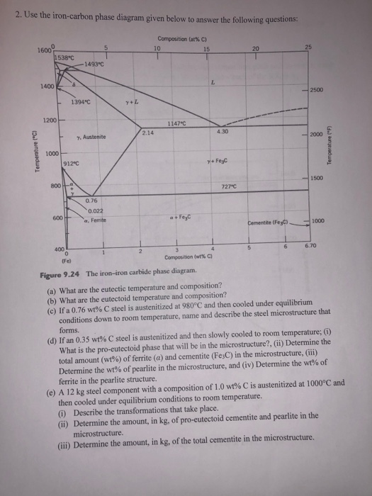
Solved 2. use the iron-carbon phase diagram given below to ...

Iron carbide (fe3c) - an overview | sciencedirect topics

Iron-carbon (fe-c) phase diagram - ppt download
Cementite - wikipedia

The iron carbon phase diagram... - metallurgical engineering ...
Coloring vector ironcarbon phase diagram stock vector ...

Iron-carbon phase diagram (note "perlite" is an alternative ...
0 Response to "40 iron carbon phase diagram calculator"
Post a Comment