41 honeywell zone control wiring diagram
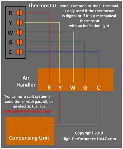
3.11.2020 · The thermostat uses 1 wire to control each of your HVAC system’s primary functions, such as heating, cooling, fan, etc. See the diagram below for what each wire controls on your system: Y – Compressor Stage 1 (Cooling) Y2 – Compressor Stage 2 (Cooling) G – Fan C – Common L/A – A – Input for heat pump fault Description: Honeywell Zone Control Wiring Diagram Honeywell Residential Zoning for Honeywell Zone Control Wiring Diagram, image size 428 X 548 px, and to view image details please click the image.. Here is a picture gallery about honeywell zone control wiring diagram complete with the description of the image, please find the image you need.
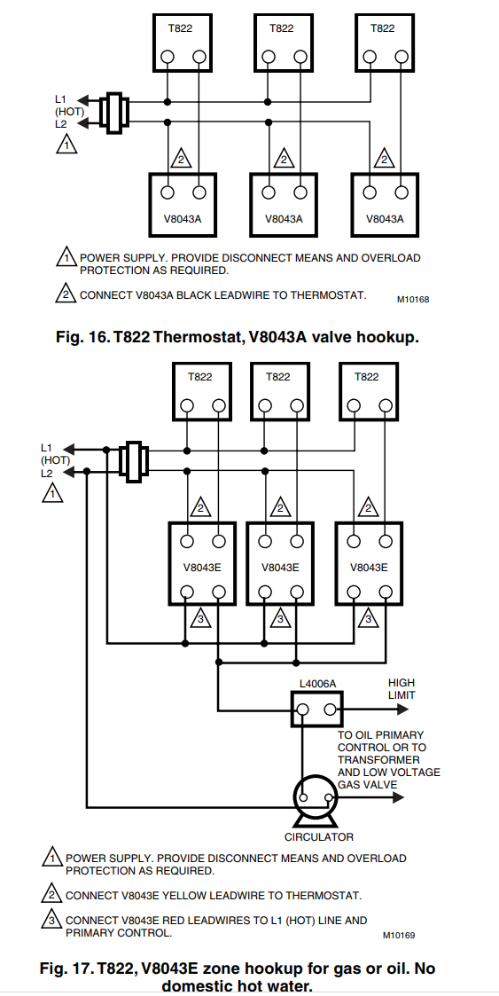
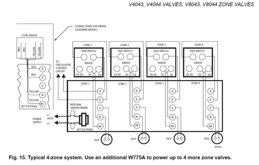
Above Honeywell zone valve wiring diagrams are from Honeywell's motorized [zone] valve installation instructions [3] Watch out : when installing zone valves not to overheat the valve or its parts. We were taught to completely remove the zone valve motor and electrical parts while sweating the zone valve to the heating system piping, but even so ...
Honeywell zone control wiring diagram
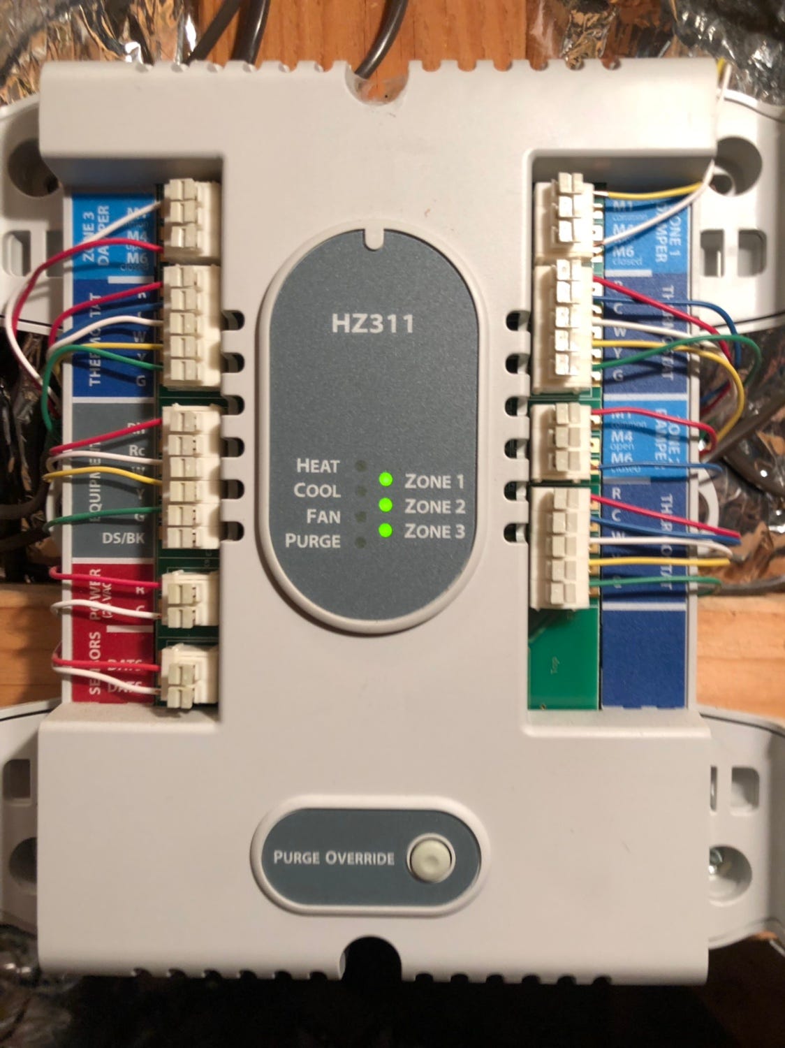
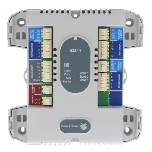
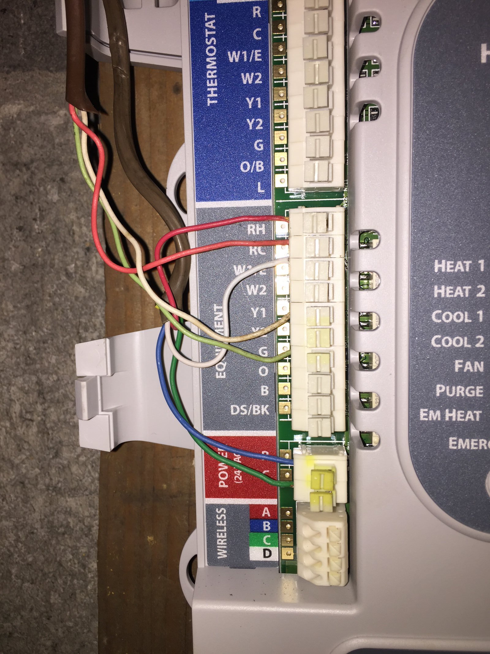
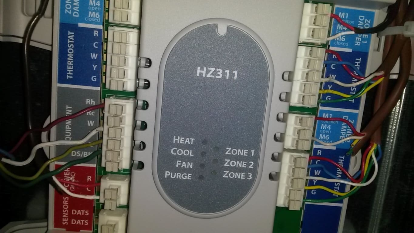
Honeywell V4044C and F 3-port hydronic valves are used in domestic and small commercial heating and cooling applica-tions to control the flow of hot or cold water. They are designed for on-off zone control of domestic sys-tems and can be used to control individual fan coil, radiator, space heater or convector applications. Connect thermostat to zone panel. To connect wire to the panel, strip approximately 1/4 in. of insulation and push wire into terminal. To release wire, press the button on top of the terminal. In retrofit applica-tions, trim end of wire if not straight. If the thermostat has separate E and Aux terminals, install a jumper between the two ... Smart Temperature Zoning. The TrueZONE® HZ311 Panel is for conventional, single stage applications for up to 3 zones (1H, 1C) at 24 Volts. It features robust push terminals, common-sense LEDs, variable-speed fan control, and leaves a smaller environmental footprint.
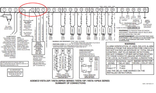
Honeywell zone control wiring diagram. View and Download Burnham SERIES 2 installation & service instructions manual online. SERIES 2 (model B) GAS BOILERS. SERIES 2 boiler pdf manual download. Also for ... Honeywell Zone Control Wiring Diagram from i0.wp.com. To properly read a electrical wiring diagram, one provides to learn how the particular components inside the system operate. For instance , when a module is powered up and it sends out a signal of half the voltage and the technician will not know this, he would think he has a challenge, as ... On the Honeywell L8148E Aquastat (used to control separate, multiple zone valves or zone circulator relay switches) the two thermostat wires will be connected to terminals marked T and TV. Call for heat, no voltage : Turn the thermostat(s) all the way UP and confirm that room temperature is below the thermostat SET temperature; the thermostat should call for heat. This thermostat provides electronic control of 24 VAC single-stage heating and cool-ing systems,or 750 mV heating systems. System Types • Gas,oil,or electric heat with air conditioning • Warm air,hot water,high-efficiency furnaces,heat pumps,steam,gravi-ty • Heat only — two-wire systems, power to open and close zone valves (Series 20 ...
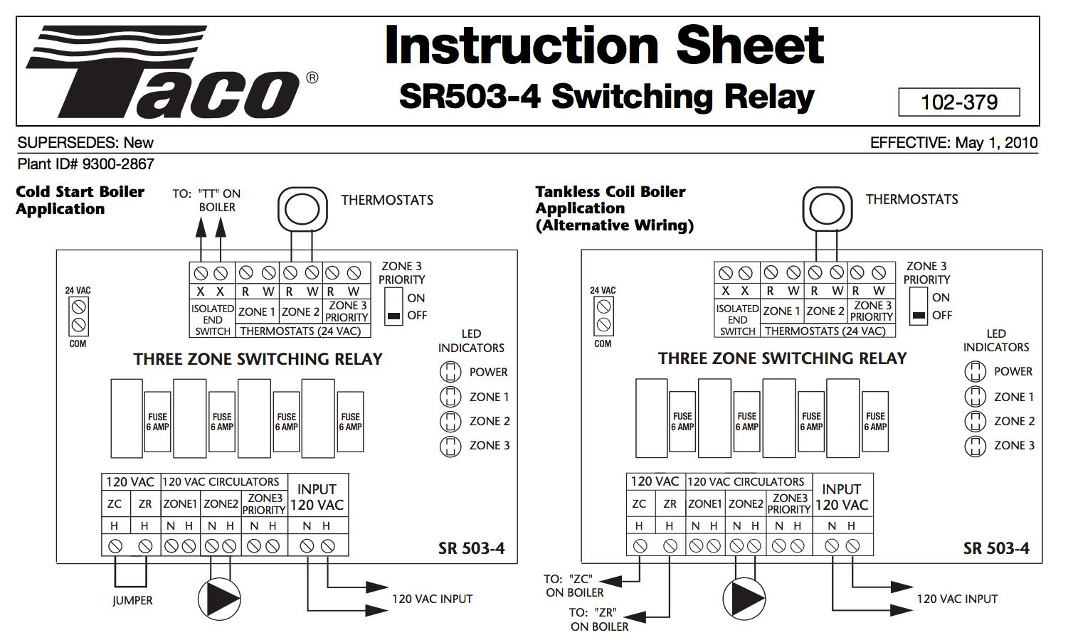
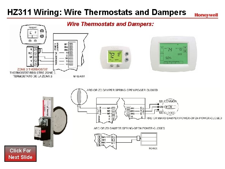
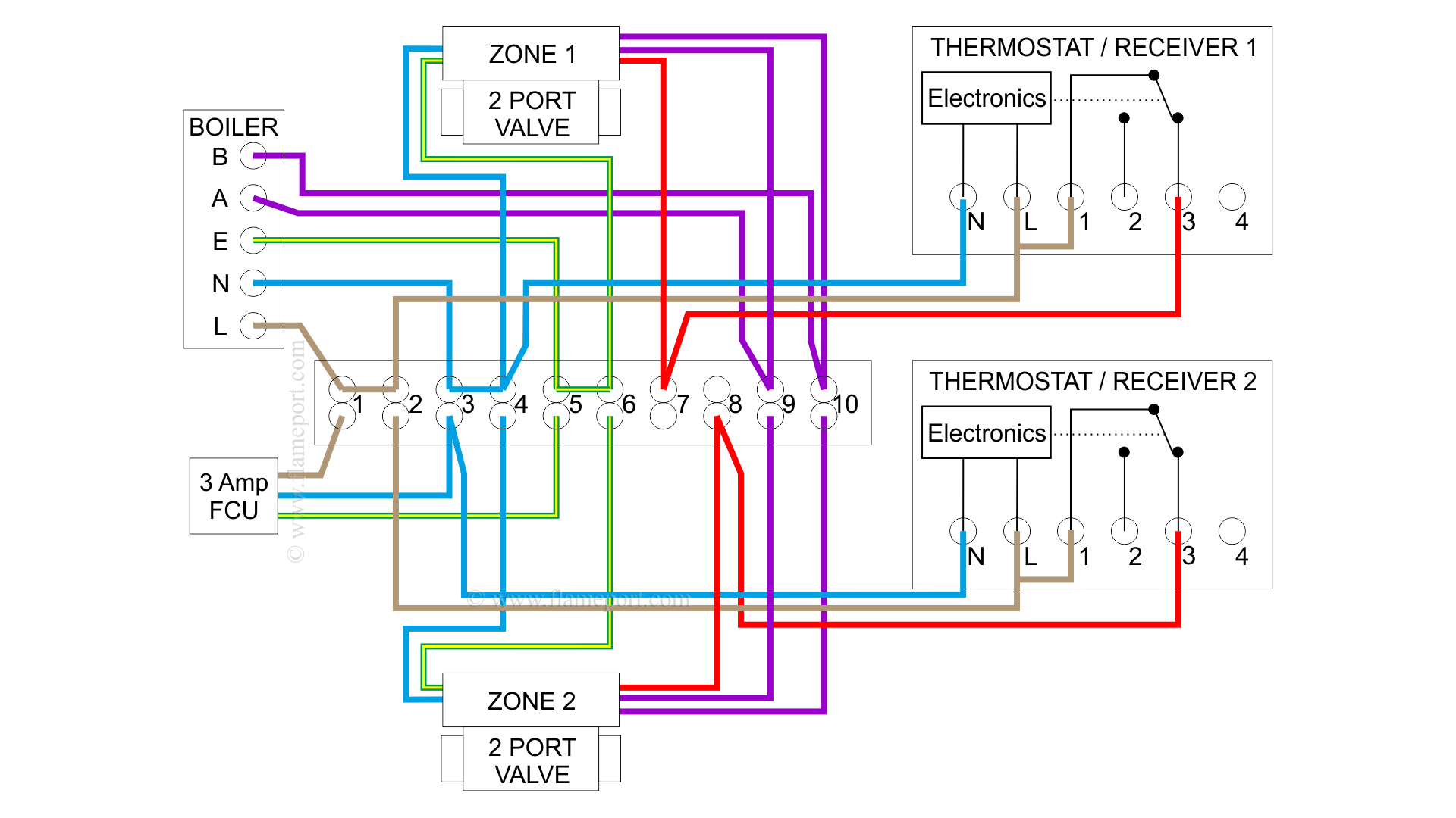
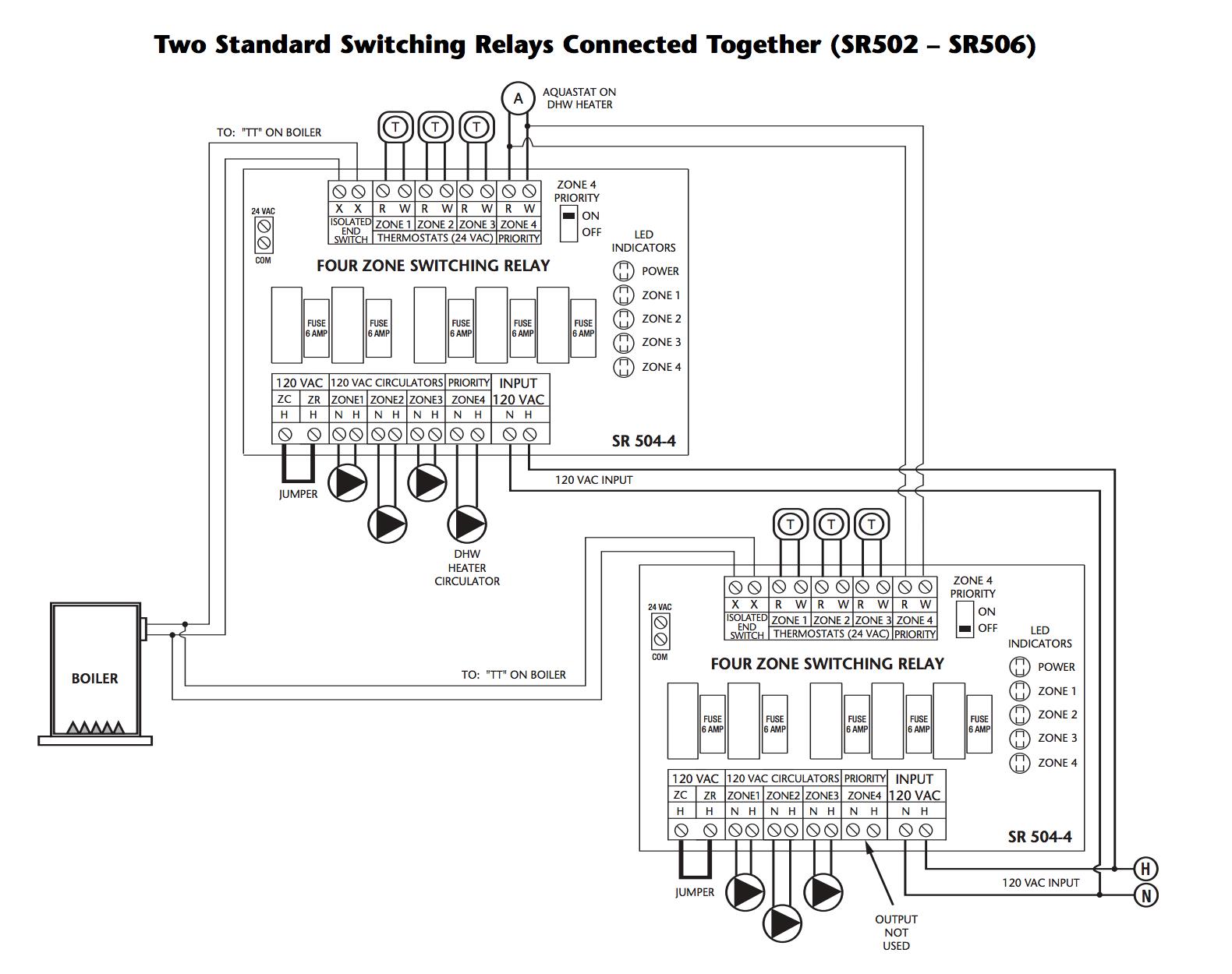
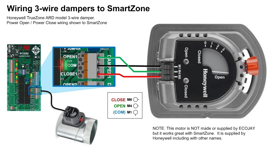
Honeywell's TrueZONE® panels can control zone valves and circulator relays in hydronic heating applications. This document provides helpful wiring diagrams to assist you in a variety of installation scenarios. HZ311 HZ322 HZ432 When using Alternative Wiring diagram, the boiler oper- ating control's ZC terminal will see the load of the circulator(s). Warning: When using Alternative Wiring diagram, wiring instructions must be followed so power originates from the boiler aquastat. Wiring must comply with applicable codes, ordinances, and regulations. Use the following wiring diagrams to wire the zone panel to the thermostats and dampers. The HZ432 offers many innovations for wire management and organization: wires can be run behind the panel, through wire channels on its sides, and attached to a wiring anchor with a ... Honeywell wiring diagrams for the correct wiring of BDR91's for Combi Boilers, Motorised Zone Valves and S Plan and Y Plan systems is on Page 44 to Page 47 of the evohome Installation Manual and the 'BDR91 reset procedure' is on Page 19, Step 1 (it says press and hold the button for 15 seconds, but in practice just press and hold until.
The following diagram is an overall view of wiring for a heat pump system as depicted in steps 3-7.Mount the HZ TrueZONE panel near the HVAC equipment; locate it on a wall, stud, roof truss, or cold-air return. NOTE: (AUTRE EMPLACEMENTThe HZ TrueZONE panel can be mounted in any orienta-tion; level it for appear-ance only. Zone Valve Wiring Manuals Installation Instructions Guide To Heating System Valves Inspection Repair. Need help wiring honeywell zone valves control valve v8043e1012 ecobee install with manuals installation boiler adding to weil mcclain he hot water piping home v4043 motorized aquastar l8048g 2 taco s plan central heating system v8043 wire diagram for at72d combination zones v8043e1412 port 5 ... Honeywell Zone Control Wiring Diagram - wiring diagram is a simplified agreeable pictorial representation of an electrical circuit. It shows the components of the circuit as simplified shapes, and the aptitude and signal connections in the middle of the devices. A wiring diagram usually gives assistance about the relative direction and ... Wiring Centre 31 Re-binding of wireless products 32 - 34 OpenTherm 34 Other information Training and further information 35 These wiring diagrams are for guidance only and at the time of publication represent the latest information available to us from other manufacturers. Honeywell reserve the right at any time and without notice to change any
Wiring Diagram Using a Zone Valve with a 24-V Thermostat and a Transformer For illustration purposes only: • Location of thermostat may vary. White Black R 110-V Power Source 24-V Thermostat (p/n 8200008) RC Y B O RH G W Zone Valve Unit Bypass Main - Back to Outdoor Furnace C W R C NOTE Thermostats must be installed by quali˜ed technician ...

Honeywell Rth9585wf Wiring Diagram. All you need to know about thermostat wiring including thermostat wires color codes, wiring diagrams, and videos to make your DIY easier. The Honeywell RTHWF/W Wi-Fi Smart Color Programmable Thermostat offers the best of both worlds in performance and versatility by utilizing.

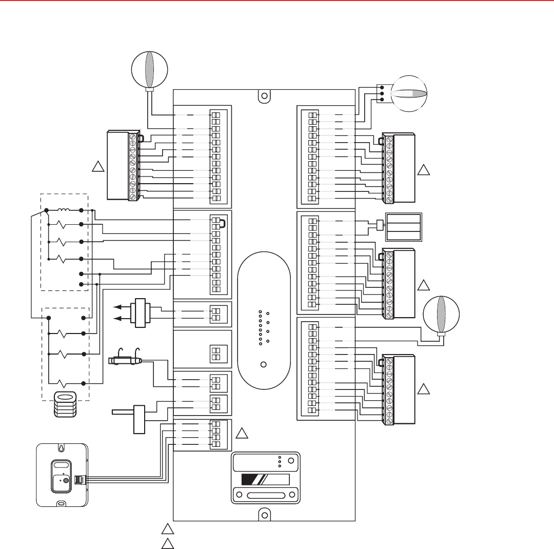
Wiring Diagram ... All signals from the HWF2-COM communicator panel are delivered to Honeywell's AlarmNet Net-work Control Center, which routes the information to the appropriate central station. Package Contents ... Zone modes are NOT a supported feature.

Wiring must comply with applicable codes, ordinances, and regulations. Use the following wiring diagrams to wire the zone panel to the thermostats and dampers. The HZ432 offers many innovations for wire management and organization: wires can be run behind the panel, through wire channels on its sides, and must be attached to a wiring anchor

In this HVACR Training Video, I Show the Wiring, Operation, Troubleshooting, and Dismantling of Honeywell 4 Wire and 5 Wire Zone Valve. I show how each part...

HOME > PROFESSIONAL ZONE > Resource Centre > Wiring Diagrams. WIRING DIAGRAMS. Our Wiring Diagrams section details a selection of key wiring diagrams focused around typical Sundial S and Y Plans. ... The Honeywell Home trademark is used under license from Honeywell International Inc. ...

Honeywell Zone Control Diagram | Wiring Diagram - Honeywell Zone Valve Wiring Diagram. Wiring Diagram not just offers detailed illustrations of everything you can do, but additionally the methods you should stick to while performing so. Not only is it possible to discover various diagrams, but you can also get step-by-step guidelines for a ...
Wiring Diagram Reference Standard Heat/Cool Conventional 9, 10 Heat Only Conventional 11 Heat Only with Fan Conventional 12 Heat Only (Series 20) Power to open and power to close zone valves Conventional 13 Normally Open Zone Valves—Heat Only Conventional 14 Cool Only Conventional 15 Standard Multistage up to 2 Heat/2 Cool Conventional 16, 17

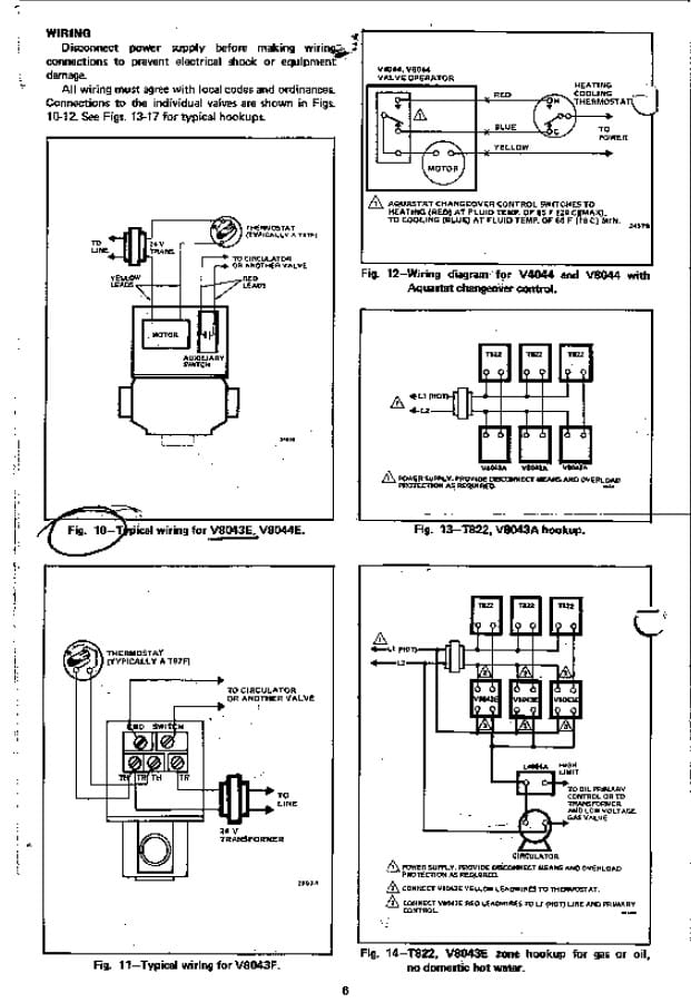
OPEN position Fig. 11 - Wiring diagram for V and V with Aquastat® Honeywell In Canada. Above Honeywell zone valve wiring diagrams are from Honeywell's motorized HONEYWELL V ZONE VALVE - [PDF installation instructions] and a single conductor may be conducted from that splice to the appropriate power and control terminals shown in the wiring diagram.

How to wire a Honeywell V8043E 1012 Zone Valve Perfectly by jerry. Note: Updated diagram at end of videoWiring drawing here: http://nakco.com/Control.Wiring...
SPlan only The wiring diagram above shows relevant connections to a Honeywell junction box Part No. S plan central heating system need help wiring honeywell zone valves y control valve v8043e1012 china 2 port motorized 5 how does an work home v4043 faqs to motorised faults free buzzing sound from S Plan Central Heating System Need Help Wiring ...
The TrueZONE® HZ322 Panel is for conventional and heat pump applications up to 3 zones (2H, 2C) at 24 Volts. It features robust push terminals, common-sense LEDs, variable-speed fan control, and leaves a smaller environmental footprint. TrueZONE® HZ322 Panel Kit. TrueZONE® HZ322 Panel Kit. TrueZONE® HZ322 Panel.
installing or servicing this control. MORE NOTE: When using zone valves for both heat and indirect, the calls must be separated in order to prioritize indirect calls. This can be accomplished by using a general purpose relay as shown above. However, for ease of installation, a zone control panel is recom-mended (see wiring diagram 7 on next page).

Honeywell Zone Valve V8043f1036 Wiring Diagram Collection. Assortment of honeywell zone valve v8043f1036 wiring diagram. A wiring diagram is a simplified conventional pictorial depiction of an electric circuit. It shows the elements of the circuit as streamlined forms, as well as the power and also signal connections between the devices. A wiring diagram normally offers information regarding…
R8285a1048 Honeywell Fan Center Relay Transformer Spdt 120v Amre Supply. Diagram Honeywell Fan Center Control Wiring Full Version Hd Quality Wiringpanels9 Indebitoilfilm It. Diagram Oil Fired Furnace Fan Center Relay Wire Full Version Hd Quality Want Monteinni It. Od 0715 Honeywell Fan Relays Wiring Diagrams Diagram.
Wiring Schematic For Honeywell Zone Valve. Amarante Pruvost. July 26, 2021. The old owner have installed 4 Honeywell VE zone. The wireless versions also control zone valve applications that provide time control of stored domestic hot water and two heating zone applications S Plan Plus. Click For A Larger View Diagram Honeywell Central Heating.
Honeywell zone control valve v8043e1012 connect to line voltage doityourself com community forums need help wiring valves adding weil mcclain he boiler heating the wall v8043 hot water piping diagram quality 1 faqs how or wire a 2 into mclain cgm 3 pi gas home v4043 motorized installation guide manuals sandy ed u can you with terry love… Read More »
Klixon wiring diagram. This FAQ is a collection of posts from the DeWalt Radial Arm Saw Discussion Forum. We have been in business in the Poconos in Pennsylvania SINCE 1959, we are Factory authorized service and warranty center for multiple tool, motor, pump, air …
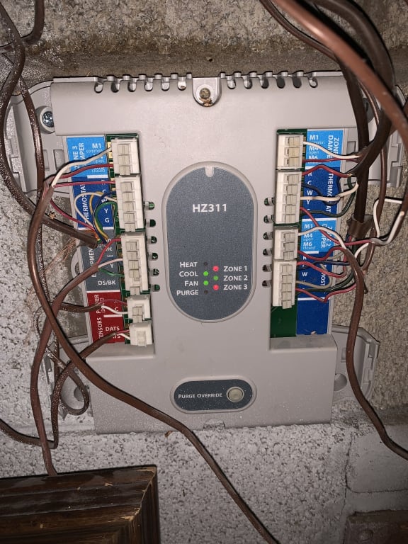
Smart Temperature Zoning. The TrueZONE® HZ311 Panel is for conventional, single stage applications for up to 3 zones (1H, 1C) at 24 Volts. It features robust push terminals, common-sense LEDs, variable-speed fan control, and leaves a smaller environmental footprint.

Connect thermostat to zone panel. To connect wire to the panel, strip approximately 1/4 in. of insulation and push wire into terminal. To release wire, press the button on top of the terminal. In retrofit applica-tions, trim end of wire if not straight. If the thermostat has separate E and Aux terminals, install a jumper between the two ...
Honeywell V4044C and F 3-port hydronic valves are used in domestic and small commercial heating and cooling applica-tions to control the flow of hot or cold water. They are designed for on-off zone control of domestic sys-tems and can be used to control individual fan coil, radiator, space heater or convector applications.


0 Response to "41 honeywell zone control wiring diagram"
Post a Comment