42 draw the shear diagram for the beam.
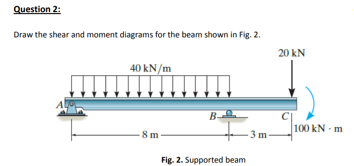
Using the slope-deflection method, determine the end moments of the beam shown in Figure 11.9a.Assume support B settles 1.5 in, and draw the shear force and the bending moment diagrams. The modulus of elasticity and the moment of inertia of the beam are 29,000 ksi and 8000 in 4, respectively.. Fig. 11.9.
Under the beam, draw your Free Body Diagram and Shear Force Diagram. 2. From left to right, make "cuts" before and after each reaction/load. To calculate the bending moment, follow the same steps we used to calculate the shear force diagram: start at x = 0 and move across the beam, calculating the bending moment at each point.
Draw the shear and bending-moment diagrams for the beam and loading shown and determine the maximum normal stress due to. draw the shear and bending-moment diagrams for the beam and loading shown and determine the maximum normal stress due to bending. Categories Uncategorized.
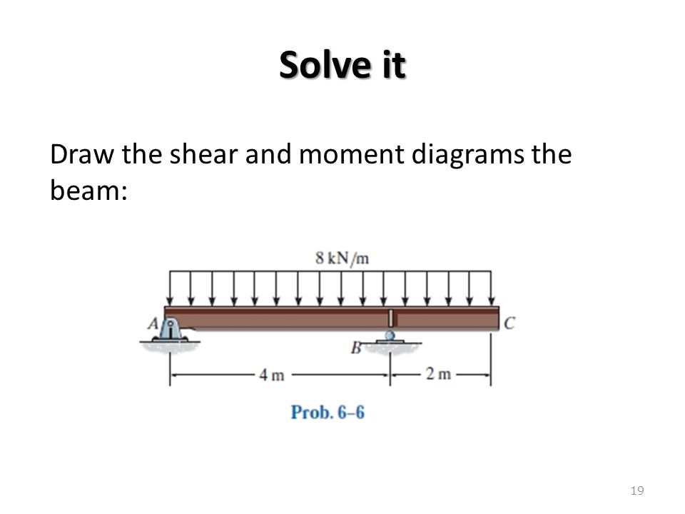
Draw the shear diagram for the beam.
Shear Force and Bending Moment Diagram Drawing Instructions. The ordinates in SFD and BMD diagrams are shear force or bending moment, and the abscissa is the length of the beam. Take a look at the left or right side of the section. On one of the portions, add the forces (including reactions) normal to the beam.
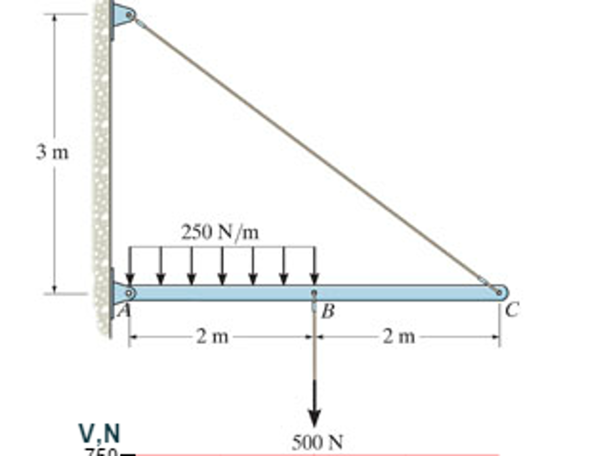
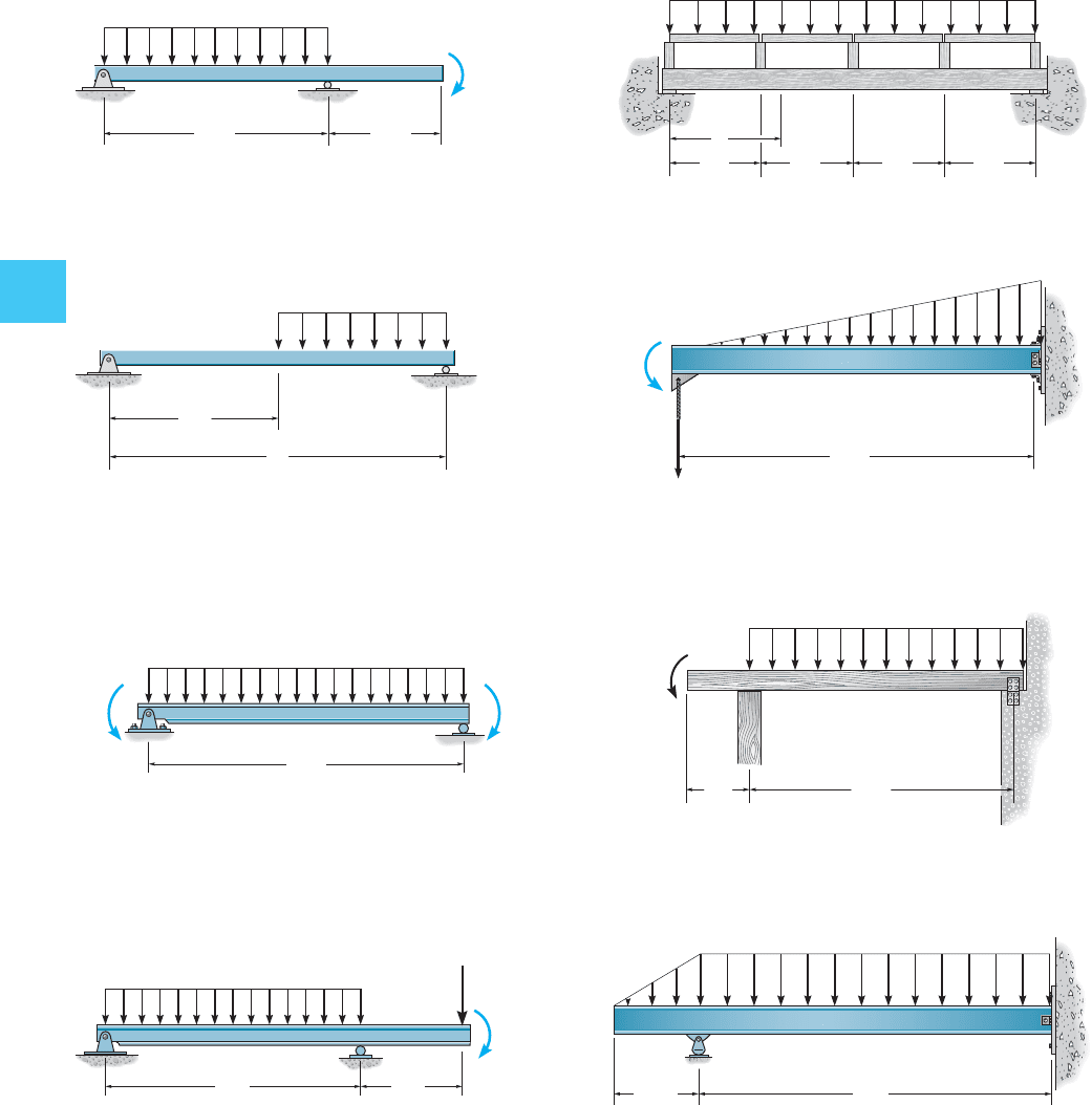
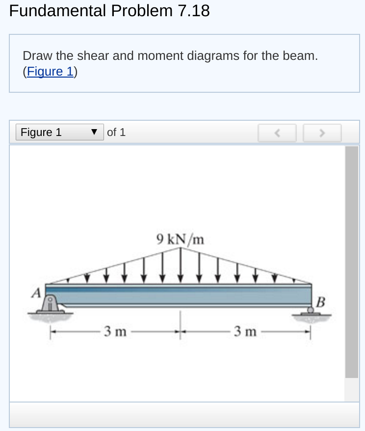
The overhanging beam in Fig. (a) carries two uniformly distributed loads and a concentrated load. Using the area method, draw the shear force and bending moment diagrams for the beam. Neglect the weight of the beam.
Cantilever Beams Moments And Deflections. Shear Force And Bending Moment Diagram For Cantilever Beam With Point Load Civil Snapshot. Draw The Shear Force And Bending Moment Diagrams For A Cantilever Beam Ab Carrying Uniform Load Of Intensity Q Over One Half Its Length Study. Mechanics Of Materials Bending Shear Stress Slender Structures Boston.
Draw the shear diagram for the beam..
How To Draw Shear Force Bending Moment Diagram Simply Supported Beam Exles Ering Intro. Bending Moment Equations Skyciv. ... beam deflection calculator maximum bending moments at the midpoint cross section of beam given by scientific diagram beam formulas with shear and mom.
Without writing the shear and moment equation of the given beam:a.draw theshear and moment diagram.b.determine the value of shear at point c.c.determine the maximum moment and indicate its location. or kay goo gle kayo mag tanong
August 7, 2021 / in Nursing Essay Help / by admin. Draw the shear and bending-moment diagrams for the beam., please draw all the detailes. Do you need a similar assignment done for you from scratch? We have qualified writers to help you.
Chapter 7. 7.35 and 7.36 For the beam and loading shown, (a) draw the shear and bending-moment diagrams, (b) determine the maximum absolute values of the shear and bending moment.. 7.35 I knew I had to separate the beam into parts so I drew FBDs of AC, CD, DE, and EB and took the summation of forces about the y axis and set it equal zero to find my unknowns for the shear diagram.
Once you have the reactions, draw your Free Body Diagram and Shear Force Diagram underneath the beam. Finally calculating the moments can be done in the following steps: 2. From left to right, make "cuts" before and after each reaction/load. To calculate the bending moment of a beam, we must work in the same way we did for the Shear Force ...
Bending moment diagrams effectively mechanicalbase draw the shear force and bending moment diagrams for beam shown below w 2500 n m f 1 10 000 study mechanics of ...
Bending moment and shear force diagram chapter 4 shear forces and bending moments solved 70 kn problem 3 draw the shear shear and moment in beams Shear Force And Bending …
The calculated shear and bending moments of a beam are almost always shown graphically as a diagram. So it important to know how to draw bending moment and shear force diagrams as an engineer, as you will likely to be asked if you apply for a mechanical or structural engineering role.
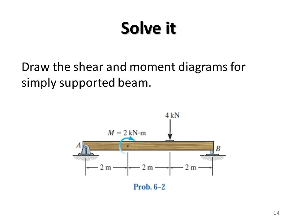
Diagrams for the cantilever beam. Draw the shear force and bending moment diagram for this loading. Fd = + 800 n. A simply supported beam with a triangularly distributed downward load is shown in fig. Draw the shear force and b.m.
Moment Diagram. 1. Point loads cause a vertical jump in the shear diagram. The direction of the jump is the same as the sign of the point load. 2. Udl result in a straight, sloped line on the shear diagram. 3. The shear diagram is horizontal for distances along the beam with no applied load. 4.
Starting at x = 0 we will move ... Draw the shear - force and bending - moment diagram s for a simple beam with a uniform load of intensity q acting over part of the span (Fig. 4-18a). For a loaded cantilever beam of unifonn cross-section, the bending moment (in N.mm) along the length is M (x) = 5x2 + 10.r , where x is the distance (in mm ...
5.3 Drawing the shear force diagram. Our approach to drawing the shear force diagram is actually very straightforward. We're going to 'trace the impact of the loads' across the beam from left to right. The first load on the structure is
Solved draw the shear diagram for the beam. draw the moment ...
The shear diagram of a beam is shown in the figure. Draw the shear diagram for the beam. 6.8.Place the appropriate function between the lines of discontinuity, ensuring the endpoints have the correct values. 1.6 2.4 (kn) 36 16 6.

Draw the shear diagram for beam | beams, bending moment, image house
Snow is 20lbs per cubic foot and last night it snowed 6in. The roof only holds the snow (ignore the weight of the beam and other loads for this thought-exercise). Horizontal beams, simply supported, 30ft long, 10' O.C.. What is the maximum vertical shear in the beam?
Solved problem 7.75 part a draw the shear | chegg.com
Guidelines to draw shear force and bending moment diagrams. During drawing of ( SF ) \text {and} ( BM ) diagrams certain specific rules and steps are require to follow. These are - First step - At first a space diagram is drawn showing full length of loaded beam, loading pattern, support points of beam, hinges or fixtures and their distances etc. ...
Solved draw the shear diagram for the beam. draw the moment ...
) Draw the Shear and Moment diagrams for the beam. Indicate values at the supports and at the points where a change in load occurs. Solution: Check Other Problems' Solutions : Book Solutions for Structural Analysis by R … (Book Solutions) Draw the Shear and Moment Diagrams for the beam.

Part a draw the shear diagram for the beam. part b draw the moment ...
Solution to problem 414 shear and moment diagrams strength of. Determine the reactions and draw the shear and bending. Assume that the beam is cut at point c a distance of x from he left support and the portion of the beam to the right of c be removed. Question 3 for the beam and loading shown on the figure below; Solved 1 draw the shear force ...
Draw the shear diagram for the beam. - studentshare
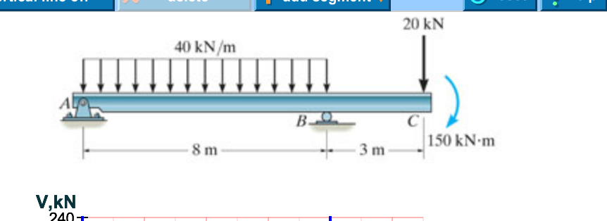
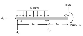
6–9. Draw the shear and moment diagrams for the beam. Hint: The 20-kip load must be replaced by equivalent loadings at point C on the axis of the beam.143 pages

Statics 7.61 - draw the shear and moment diagrams for the beam.
Civil Engineering questions and answers. Draw the shear diagram for the beam Assume that M = 200 Ib. middot ft, and L = 20 ft. Begin by placing the lines of discontinuity. Place the appropriate function between the lines of discontinuity, ensuring the endpoints have the correct values.

For the figure below, draw the shear and moment diagrams for the ...
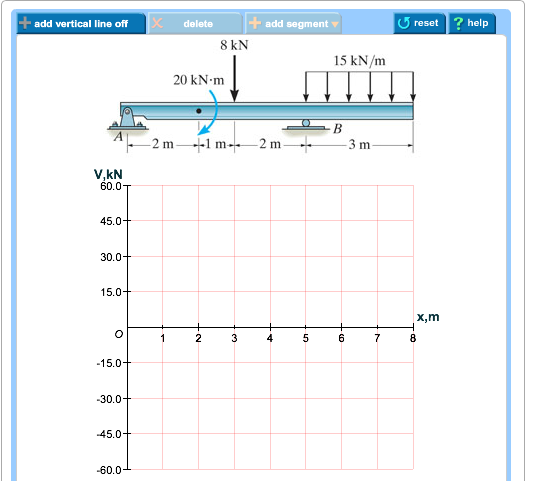
Question: Problem 7.53 5 of 6 Part A Draw the shear diagram for the beam. Click on "add vertical line off" to add discontinuity lines.

Statics 7.71 - draw the shear and moment diagram for the beam ...
Transcribed image text: Problem 6.13 Part A Draw the shear diagram for the beam. Assume that Mo 200 lb.ft, and L 20 ft. Begin by placing the lines of discontinuity. Place the appropriate function between the lines of discontinuity, ensuring the endpoints have the correct values Note Make sure you place only one vertical line at places that ...
Hibbeler r.c. structural analysis
Question: 7.78 Draw the shear and moment diagram for the beam. This problem has been solved! See the answer ...
Solved draw the shear diagram for the beam. draw the | chegg.com
Calculating Shear Force Diagram - Step 2: Keep moving across the beam, stopping at every load that acts on the beam. When you get to a load, add to the Shear Force Diagram by the amount of the force. In this case we have come to a negative 20kN force, so we will minus 20kN from the existing 10kN. i.e. 10kN - 20kN = -10kN.
Answered: draw the shear diagram for the beam.… | bartleby
Draw the moment diagram for the beam. add vertical line off V(lb 1,000 750 500 250 250 -500 750 1,000. Show transcribed image text. Expert Answer.
Draw the shear diagram for the beam - home work help - learn cbse ...
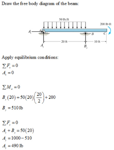
Determine the reactions at support using the free body diagram of the entire beam and equilibrium conditions. Consider the section AB alone and derive the equation of shear force and bending moment for any distance x from point A .

Solved) - part a draw the shear diagram for the beam. part b draw ...
Draw the shear diagram for the beam. Draw the moment diagram for the beam. PLEASE HELP! NOT SURE WHAT I AM DOING WRONG! Image for Draw the shear diagram for ...
Bending shear and moment diagram, graphical method to construct ...
Dec 08, 2021 · The shear diagram of a beam is shown in the figure. Draw the shear diagram for the beam. 6.8.Place the appropriate function between the lines of discontinuity, ensuring the endpoints have the correct values. 1.6 2.4 (kn) 36 16 6. 6-9.

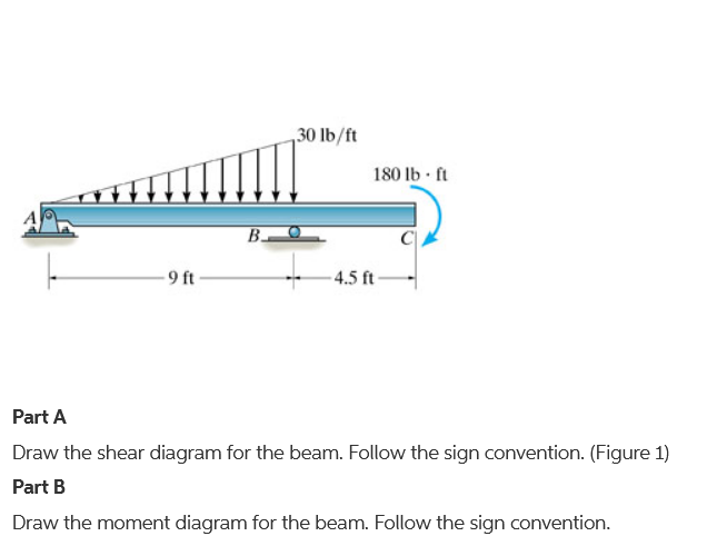
Draw the shear diagram for the beam. follow the sign convention ...
Transcribed image text: Problem 7.53 Part A Draw the shear diagram for the beam Click on "add discontinuity" to add discontinuity lines.
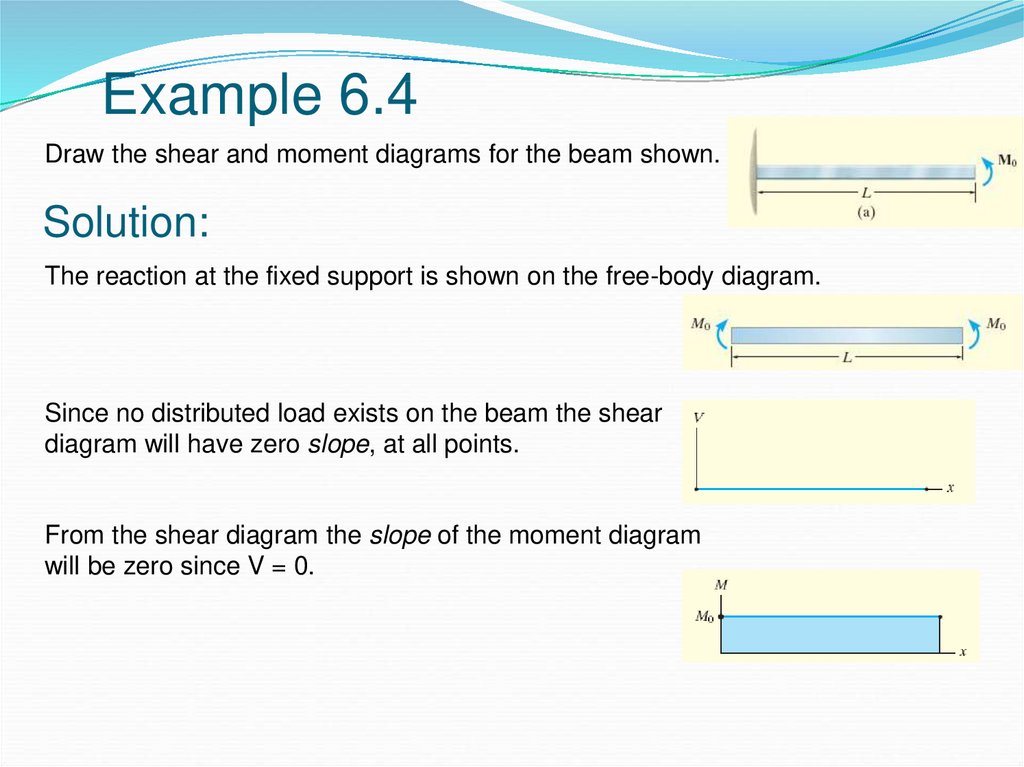
Unit 6: bending\. shear and moment diagrams - online presentation
Draw the shear diagram for the beam. 6.30. In which one is at the free end and another is 3m from the left support. (b) show the direction of the principal tensile stresses at middepth at points a, b, and c. This problem has been solved!

Drawing shear and moment diagrams for beam - youtube
Transcribed image text: Problem 7.53 Part A Draw the shear diagram for the beam. Click on "add discontinuity" to add discontinuity lines.

Draw the shear and moment diagrams for the cantilever beam in fig ...
Solved) - draw the shear force and bending moment diagrams for the ...
Answered: draw the shear and moment diagrams for… | bartleby
Solved] draw the shear force bending moment diagrams of the beam ...

Part a draw the shear diagram for the beam. follow the… - itprospt

Draw the shear diagram and the moment diagram for the beam 400 lb ...

Please answer this question in one hour. problem 6.13 part a draw ...

Solved 7.78 draw the shear and moment diagram for the beam ...
Draw the shear diagram for the beam. draw the moment diagram for ...

For the figure below, draw: a) draw the shear diagram for the beam ...

Engineering mechanics statics pages 351 - 400 - flip pdf download ...
Shear diagram - beam with 3 supports | physics forums
Bending shear and moment diagram, graphical method to construct ...
Solved) - draw the shear and moment diagrams for the beam. (figure ...

Draw the shear-force and bending-moment diagrams for the beam ...
Answered: draw the shear diagram for the beam.… | bartleby

How to calculate and draw shear and bending moment diagrams : 13 ...
How to draw shear force and bending moment diagrams (strength of ...

Drawing shear and moment diagrams for beam
Solved part a - draw the shear diagram for the beam. follow ...

Moment diagrams constructed by the method of superposition - mo ...
The ultimate guide to shear and moment diagrams | degreetutors.com

Draw shear force and bending moment diagram for cantilever beam ...
0 Response to "42 draw the shear diagram for the beam."
Post a Comment