42 functional flow block diagram
Very in depth article on functional block diagrams. FBD can make ones life so much easier when the complexity of ladder and instruction list just becomes so messy. Thanks for the article. Ashwin Patel. March 21, 2019 at 9:02 am. Heart ♥ touching. peter. March 21, 2019 at 4:58 pm.
1 T p a b 1 D e 1 1 I W t A r p t f v 1 I h T tw S r d r O w O p a.3 Purpose he purpose rior to form s the Desig y Section 5.4 Methods esign, dev stablished p.5 Mission .5.1 Phas
Extended Functional Flow Block Diagram (eFFBD) eFFBDs show the interaction between system functions by distributing them along a timeline. A timeline consists of a set of directed arrows, connecting functions and nodes to depict a processing sequence. The timeline effectively constitutes a flow of control. No data flows along the timeline, it ...

Functional flow block diagram
ConceptDraw DIAGRAM diagramming and vector drawing software extended with Block Diagrams Solution from the "Diagrams" Area is a powerful Block Diagram Creator. Cross-Functional Flowchart Cross-Functional Flowchart - to draw cross functional process maps is by starting with a cross-functional flowchart samples and templates.
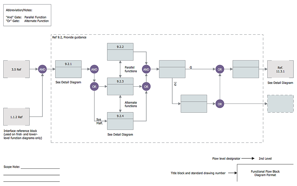
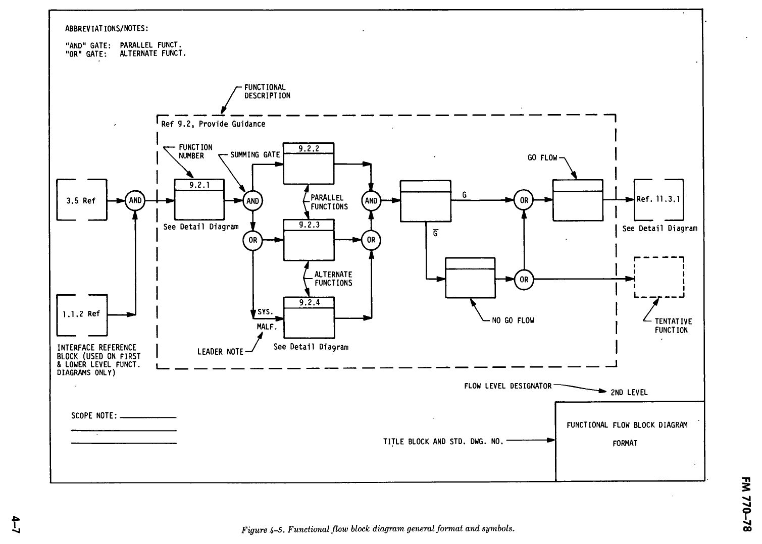
11 templates. Online Shopping Functional Flow Block Diagram. Functional Flow Block Diagram Notation illustrated. Flow direction. Provide context in a particular FFBD. Functional Flow Block Diagram Format. Breakdown FFBD. FFBD for Function 0. Functional Flow OR symbol illustration.
Create Functional Flow Block Diagram diagrams easily with the drag and drop editor and keep your design in a cloud workspace and work collaboratively with your team. You can also export and share your works via a collection of image and document formats like PNG, JPG, GIF, SVG and PDF. We come with a rich set of Functional Flow Block Diagram ...
Functional flow block diagram.
June 1962. A functional block diagram, in systems engineering and software engineering, is a block diagram. It describes the functions and interrelationships of a system. The functional block diagram can picture: Functions of a system pictured by blocks input and output elements of a block pictured with lines
A primary functional analysis technique is the Functional Flow Block Diagram (FFBD). Purpose: to show the sequential relationship of all functions that must be ...
block diagram noun: block diagram; plural noun: block diagrams. a diagram showing in schematic form the general arrangement of the parts or components of a complex system or process, such as an industrial apparatus or an electronic circuit. flow chart
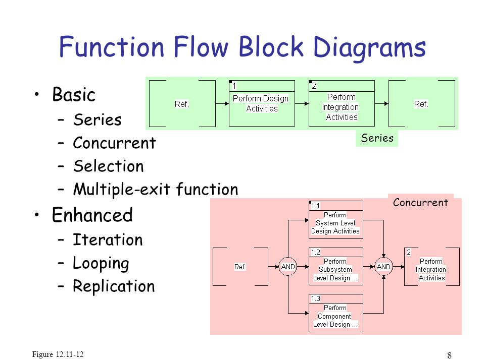
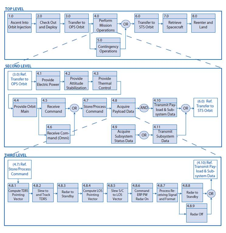
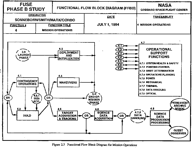
Functional Flow Block Diagrams (FFBD) surfaced in the 1950s. They are a way of illustrating and describing the processes in a development and production system environment and are a multitiered, time-sequenced, step-by-step flow diagram of a system's functional flow.
A CONOPS should contain a conceptual view of the system (i.e., a preliminary functional flow block diagram or operational architecture) that illustrates the top-level functional threads in the proposed system or situation. A CONOPS should define any critical, top-level, performance requirements or objectives stated either qualitatively or quantitatively (including system …
Functional analysis is a continuation of Use Case scenario refinements, using diagrams describing the behavior of a system, e.g., SysML Activity, SysML Sequences, or SysML State Machine diagrams. A new SysML Activity diagram should be created for every function of a Use Case allocated to a particular block or part.
A functional analysis looks at the 'functional' steps that are required to perform an aspect of a system. In this course, we will use the traditional techniq...
ConceptDraw DIAGRAM extended with Windows 8 User Interface solution from the Software Development area is the best gui software. Using the drawing tools, libraries of vector objects, graphical user interface examples that offers Windows 8 User Interface solution, you will easily design the Windows 8 user interfaces and Windows 8 UI design patterns of any complexity.
Figure 5 presents information in an N2 diagram, which complements the Functional flow block diagram. Notice that in this illustration, there are no data elements or triggers. The figure illustrates the context between functions at different levels of the model. Examples
A functional flow block diagram illustrates the step-by-step sequence of a development and production system. Transfer Function Block Diagram A transfer function block diagram works by adding one input at a time and mark the remaining as zero. More Templates ...
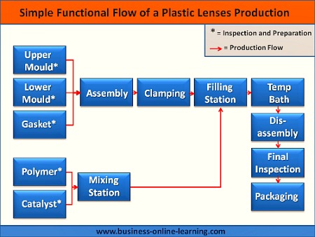
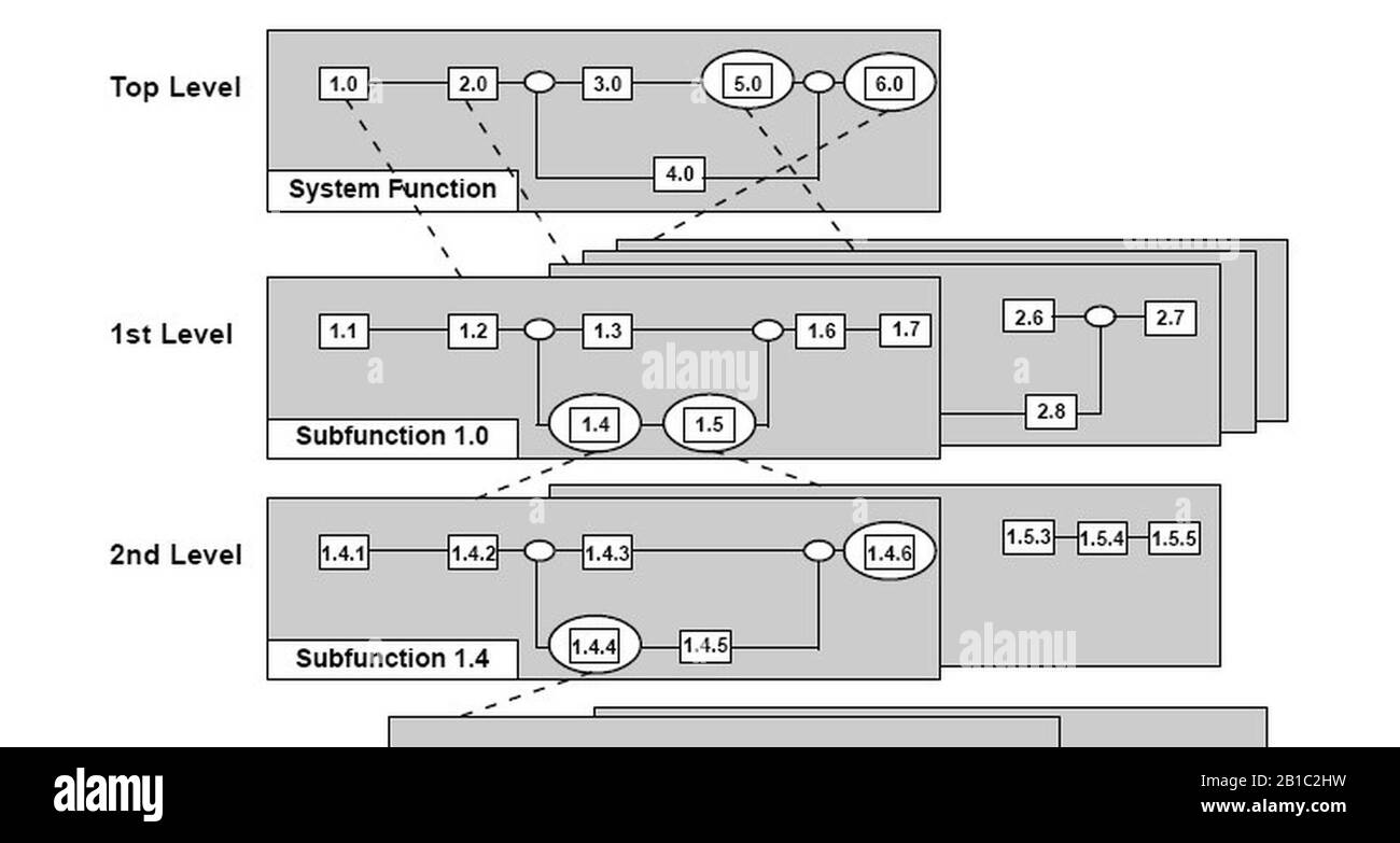
Functional Flow Block Diagrams may have been around for a few decades, but they still have their uses in business process mapping. Their focus is the order of execution of tasks or functions in a sequence of ordered blocks. Each functional block can be further broken down in a separate diagram showing the sub-tasks within each functional block.
The functional flow block diagram (FFBD) is a multi-tier, time-sequenced, step-by-step flow diagram of the system’s functional flow. The diagram is developed in the 1950s and widely used in classical systems engineering.The functional flow block diagram is also referred to as Functional Flow Diagram, functional block diagram, and functional flow.
A Functional Block Diagram is a visual tool to describe the operation, interrelationships and interdependencies of the functions of a system or equipment. By making the primary functions of the equipment visible, it allows the FMEA team members to agree on how the system works and identify the beginning and end of system or equipment operation.
About Press Copyright Contact us Creators Advertise Developers Terms Privacy Policy & Safety How YouTube works Test new features Press Copyright Contact us Creators ...
Use Case Diagram Templates by Visual Paradigm. A UML use case diagram is visual representation of system/software requirements. A use case diagram consists of the system, the related use cases and actors and relates these to each other to …
Functional Flow Block Diagrams (FFBD) can be process-oriented models that represent functions as nodes and objects as the connecting links. Nodes are typically labeled but links are typically unlabeled in process-oriented FFBDs. Figure 6-21 is a FFBD for two of the functions of a digital camera.
F-111 Functional Flow Block Diagram [classic] Use Creately's easy online diagram editor to edit this diagram, collaborate with others and export results to multiple image formats. You can edit this template and create your own diagram. Creately diagrams can be exported and added to Word, PPT (powerpoint), Excel, Visio or any other document.
Functional Flow Block Diagram of System As shown in the diagram, a central processing unit performs functions, receives inputs from the user, and converts them into outputs to display to the user via output devices. This is the Functional Block Diagram of a typical process that occurs in a computer system. This was illustrated by computer system engineers differently using different …
Block Diagrams In the introductory section we saw examples of block diagrams to represent systems, e.g.: Block diagrams consist of Blocks-these represent subsystems - typically modeled by, and labeled with, a transfer function Signals- inputs and outputs of blocks -signal direction indicated by arrows -could be voltage, velocity, force, etc.
What is Functional Block Diagram (FBD)? The primary concept behind an FBD is data flow. A Functional block diagram describes a function between input and output through a functional block. A FBD program is built using function blocks connected together to define the data exchange. The connecting lines will have...
This approach allows for activity hierarchies, solving the need to create Functional Flow Block Diagrams (FFBD). Activities are allocated to the system structural elements via the <<allocation>> relationship. The major downside to this approach is the inability to see the big picture.
Functional Flow Block Diagrams ♦A primary functional analysis technique is the Functional Flow Block Diagram ( FFBD). ♦Purpose: to show the sequential relationship of all functions that must be accomplished by a system. ♦Each function (represented by a block) is identified and described in terms of inputs, outputs, and interfaces from top down
Function Flow Block Diagram (FFBD) FFBDs have the classic features of logic structures and control flow. Part of the behavioral (logical architecture) representation set, they unambiguously represent the flow of control through sequencing of functions and constructs, focusing exclusively on structural control and ignoring the sequencing and synchronization aspects of the corresponding data flow.
WITH FUNCTIONAL FLOW BLOCK DIAGRAMS AND UML-SE FUNCTIONAL FLOW REQUIREMENTS Figures 1 and 2 show an example EFFBD that will be referenced in the comparison, with one of the elements in Figure 1 decomposed into the diagram in Figure 2. Figure 3 gives the corresponding UML 2 Activity Dia-gram. Both EFFBD and Activity Diagrams give the
29 Oct 2021 — Functional Flow Block Diagrams (FFBD) are multi-tier, time-sequenced, step-by-step flow diagram of the system's functional flow. See also.
A Functional Flow Block Diagram (FFBD) is a simple way to show the sequential relationships between a set of Functions . The original concept can be extended to make it more useful to later stages of Developmental Engineering, having little arcane symbology and requiring no proprietary software tools 1 .
"Functional Flow Block Diagram", or "FFBD", is a time-sequenced and "step-by-step" flow diagram, with the help of which it is convenient to describe some system's functional flow. The "Functional Flow Block Diagram notation" was developed in the 50s, and it is quite widely used in classical systems engineering.
07.06.2021 · It should contain a conceptual view of the system (i.e., a preliminary functional flow block diagram or operational architecture) that illustrates the top-level functional threads in the proposed system or situation. This provides a bridge between the often vague capabilities that a project begins with and the specific technical requirements needed to make it successful. A …
The main goal of drawing a block diagram is to give an overview of the workflow that could be expected from the system post its completion. With the clear illustration, it becomes easy for the engineers to assess the smooth functioning of the process and to identify the existing elements (or the missing ones) that might obstruct, hinder, or unnecessarily delay the output.
Block diagram template
A functional flow block diagram ( FFBD) is a multi-tier, time-sequenced, step-by-step flow diagram of a system 's functional flow. The term "functional" in this context is different from its use in functional programming or in mathematics, where pairing "functional" with "flow" would be ambiguous.
as: functional-flow block diagrams, timeline analysis sheet, requirements allocation sheet, Integrated Definition, and others. • Use of the tools illustrated in this chapter is not mandatory, but the process they represent is: - Define task sequences and relationships (functional flow block diagram (FFBD)), - Define process and data flows ...
A multi-tiered, time-sequenced, step-by-step flow diagram of a system's functional flow is known as a functional flow block diagram (FFBD). In this sense, the term "functional" is distinct from its application in functional programming or mathematics, where the combination of "functional" and "flow" would be confusing.
A functional flow block diagram (FFBD) is a multi-tier, time-sequenced, step-by-step flow diagram of a system's functional flow. The term "functional" in this context is different from its use in functional programming or in mathematics, where pairing "functional" with "flow" would be ambiguous. Here, "functional flow" pertains to the sequencing of operations, with "flow" arrows expressing ...








![PDF] FUNCTIONAL FLOW BLOCK DIAGRAM WITH UML FOR TEST ...](https://d3i71xaburhd42.cloudfront.net/fe1e44f5e482b1e0b199871110cc72e3d5ade40e/3-Figure3-1.png)


![PDF] Formalizing Functional Flow Block Diagrams Using Process ...](https://d3i71xaburhd42.cloudfront.net/f19ccd80d1359160172f181b987dfda99d804509/2-Figure1-1.png)




0 Response to "42 functional flow block diagram"
Post a Comment