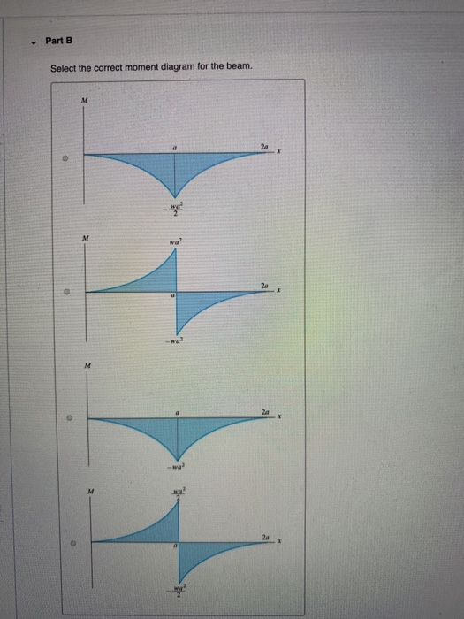
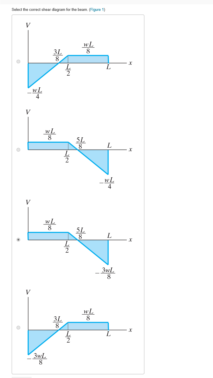
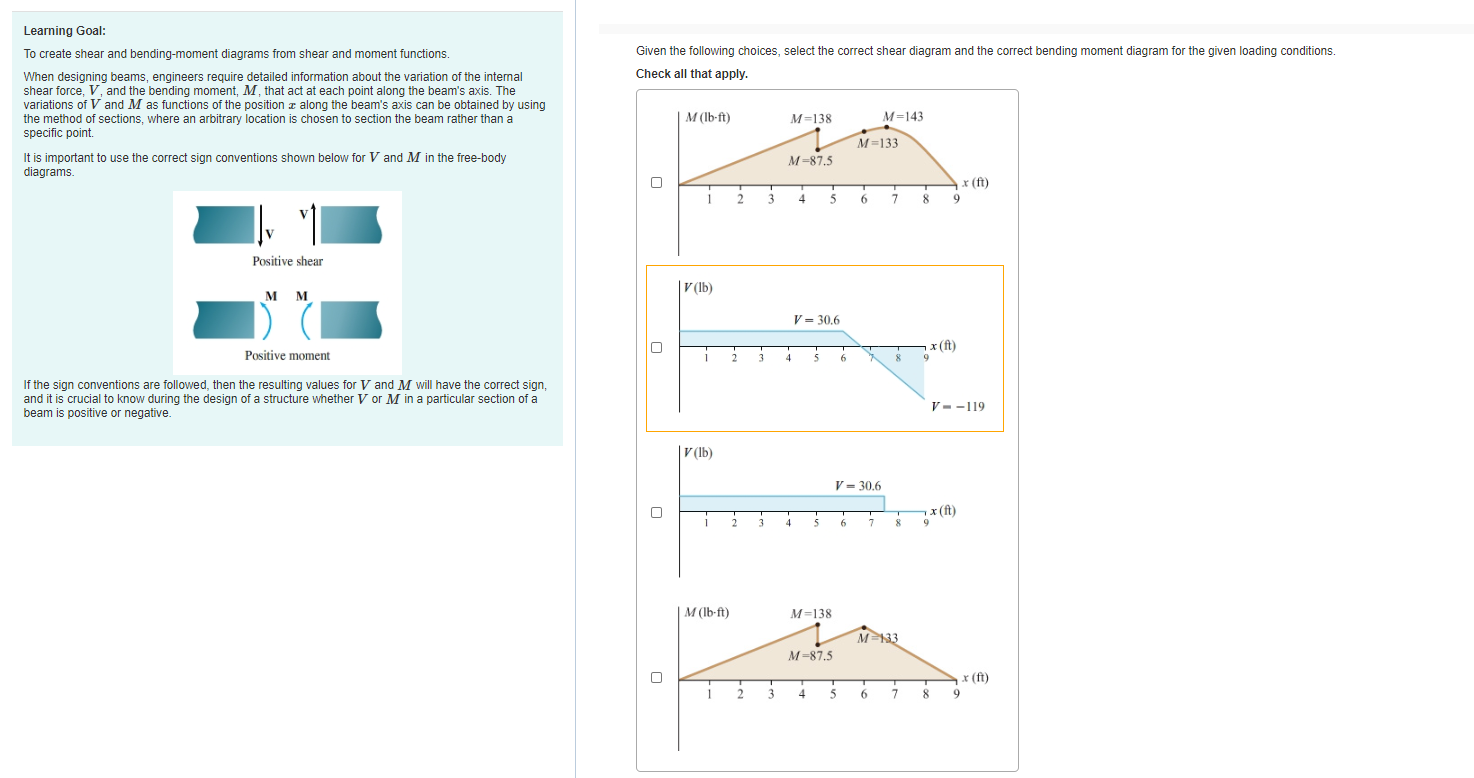
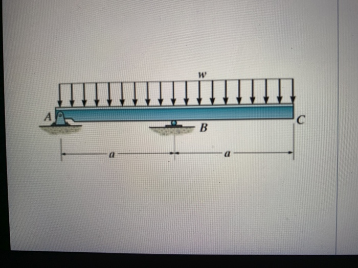
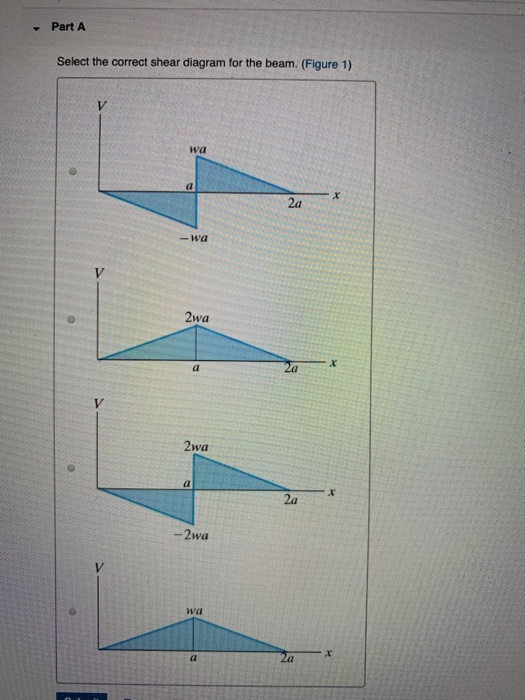
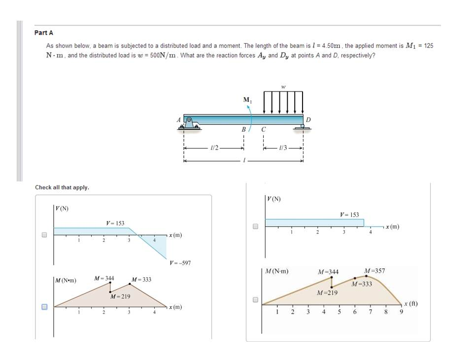
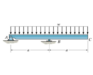
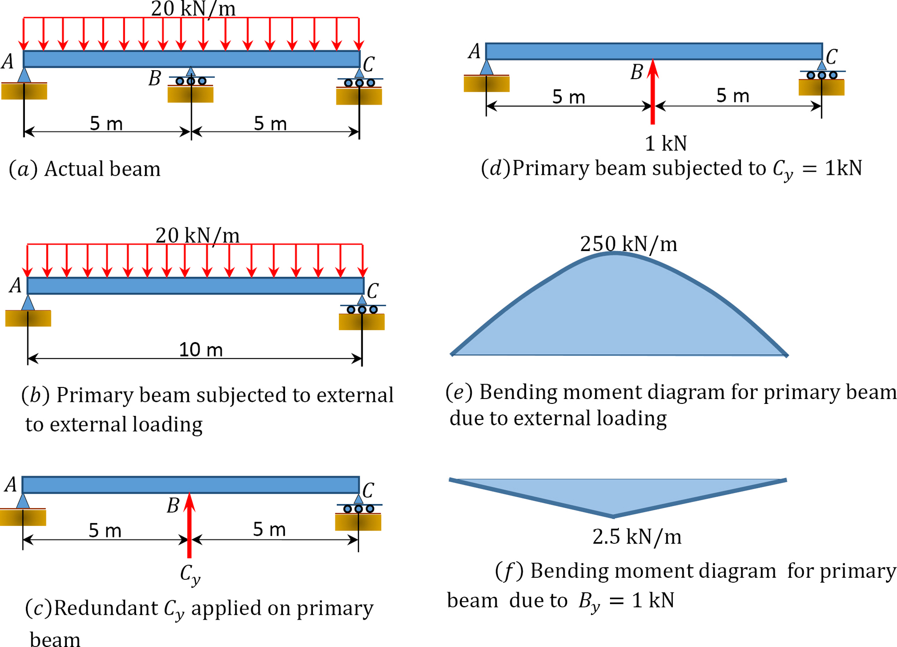
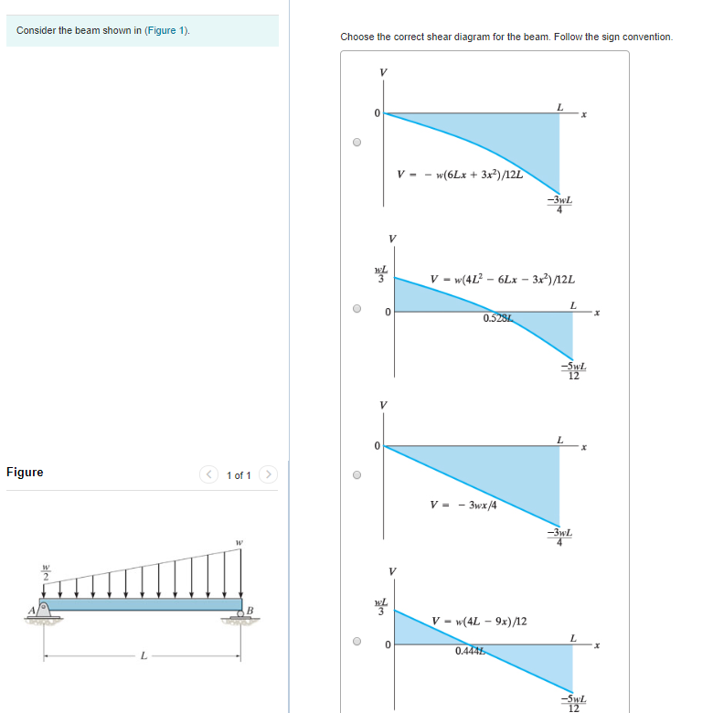
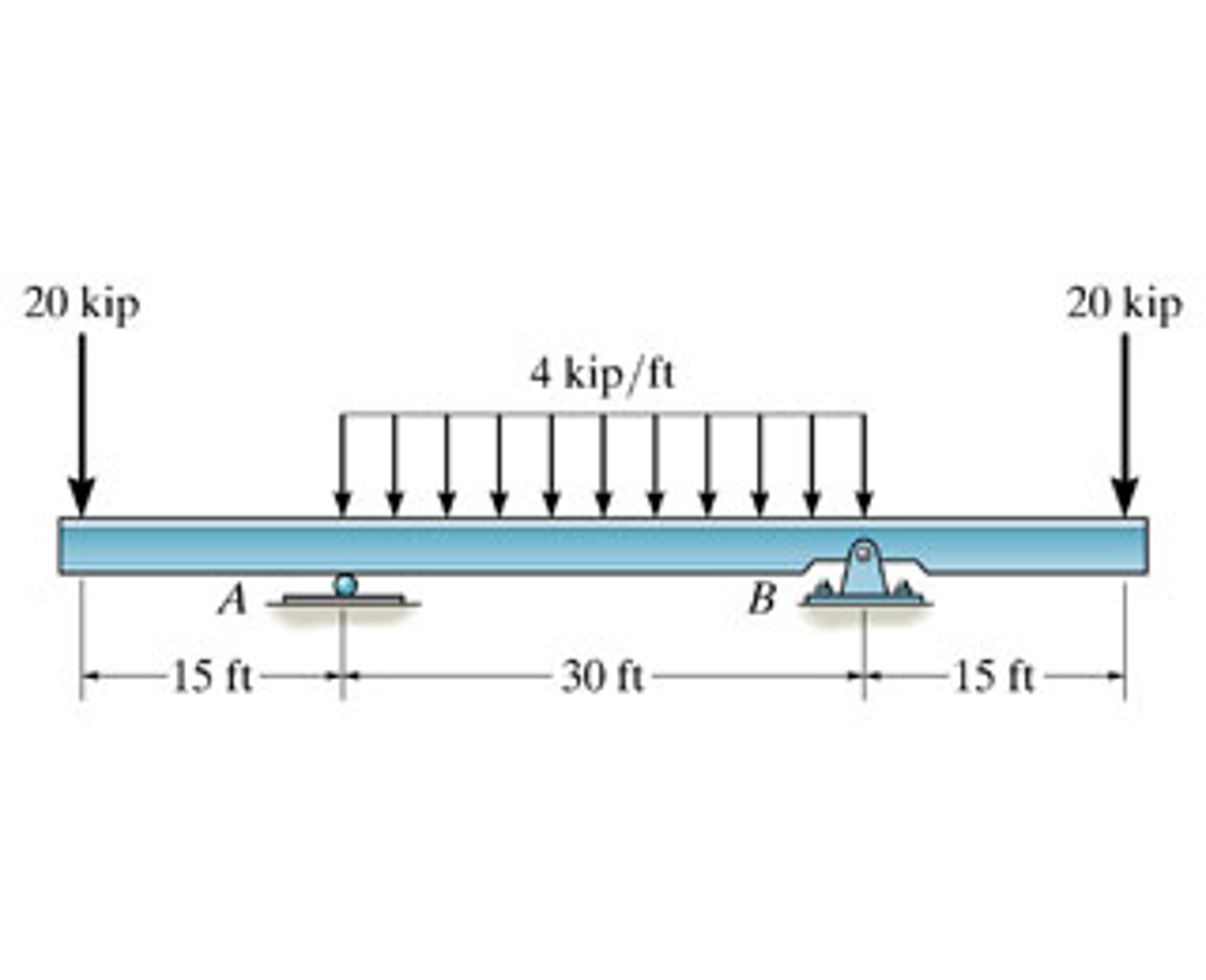
42 select the correct shear diagram for the beam.
Draw The Shear And Moment Diagrams For Cantilever Beam. A Cantilever Beam Ab Is Subjected To Uniformly Distributed Load As Shown In Figure Ex 3 Determine Reactions At Supports And B Draw The Shear Force Bending Moment Diagrams. Sketch The Shear And Bending Moment Diagrams For Cantilever Beam Shown Given Following Parameters Omega A L Study.
Drawing Forces in the Beam: 12. Draw a diagram of the shear force in the beam. The shear in the end of the beam starts out at 0 lbs. However, since there is a reaction of 22,500 lbs on the left side of the beam, it will create that much shear in that location. The line load will cause this shear to decrease along the length
Calculating Shear Force Diagram - Step 2: Keep moving across the beam, stopping at every load that acts on the beam. When you get to a load, add to the Shear Force Diagram by the amount of the force. In this case we have come to a negative 20kN force, so we will minus 20kN from the existing 10kN. i.e. 10kN - 20kN = -10kN.
Select the correct shear diagram for the beam.
Transcribed image text: Select the correct shear diagram for the beam. (Figure 1) 2wa Figure ( 1011 2wa -2wa Select the correct moment diagram for the beam ...
For The Beam And Loading Shown A Select Correct Shear Bending Moment Diagrams B Determine Equations Of Curves Study. Problem 9 1 Two Beam Segments Ac And Cd Are Connected Together At C By A Frictionless Pin Segment Is Cantilevered From R. 329 6 1 Draw The Shear And Moment Diagrams For Shaft Bearings At A B Exert Only Vertical Reactions On.
For The Beam And Loading Shown A Select Correct Shear Bending Moment Diagram s B Determine Equations Of Curves Study. Problem 9 1 Two Beam Segments Ac And Cd Are Connected Toge the r At C By A Frictionless Pin Segment Is Cantilevered From R. 329 6 1 Draw The Shear And Moment Diagram s For Shaft ...
Select the correct shear diagram for the beam..
Transcribed image text: Select the correct shear diagram for the beam. 2wa x 2a b) wa a 2a wa MacBook Air a) 2wa X a 2a b) wa a 2a x V wa c) a x 2a - wa V ...
1 week ago - How to Calculate Shear Force Diagram (SFD) of a Simple Beam? In this tutorial, we will look at calculating the shear force diagram of a simple beam. This is an important concept to understand, as shear force is something a beam will need to be checked for, for a safe design.
Ask any question and get an answer from our subject experts in as little as 2 hours.
Draw shear force and bending moment diagram. Calculate the shear force and bending moment for the beam subjected to an uniformly distributed load as shown in the figure, then draw the shear force diagram (SFD) and bending moment diagram (BMD). 5 kN/m 3 m A B EXAMPLE 6 If we have bending moment diagram then just by differentiating the shear at ...
Shear and moment diagrams and formulas are excerpted from the Western Woods Use Book, 4th edition, and are provided herein as a courtesy of Western Wood Products Association. Introduction Notations Relative to “Shear and Moment Diagrams” E = modulus of elasticity, psi I = moment of inertia, in.4 L = span length of the bending member, ft.
shearand bending moment diagrams. The basic procedure for determining the shear and moment diagrams is to determine the values of V and M at various locations along the beam and plotting the results. In doing so, we will determine critical sections within the beam. A critical section is one where a critical or maximum stress occurs.
Select the correct shear diagram for the beam. (figure 1) Dec 31, 2020 · Example 1: internal actions at a section cut of a simply supported beam. For the following simply supported beam, loaded by a uni for m distributed load: Find the bending moment and the transverse shear for ce at the middle span; Find the bending moment and the transverse shear for ce as a function of distance x from ...
beam from the left hand end and summing up the areas of shear force diagrams using proper sign convention. xThe process of obtaining the moment diagram from the shear force diagram by summation is exactly the same as that for drawing shear force diagram from load diagram.
Choose the correct shear diagram for the beam. Follow the sign convention. x=1.005 m. A uniform beam has a mass of 18 kg and rests on two surfaces at points A and B. Determine the maximum distance x to which the girl can slowly walk up the beam before it begins to slip. The girl has a mass of 50 kg and walks up the beam with a constant velocity.
Free online beam calculator for generating the reactions, calculating the deflection of a steel or wood beam, drawing the shear and moment diagrams for the beam. This is the free version of our full SkyCiv Beam Software. This can be accessed under any of our Paid Accounts, which also includes a full structural analysis software.
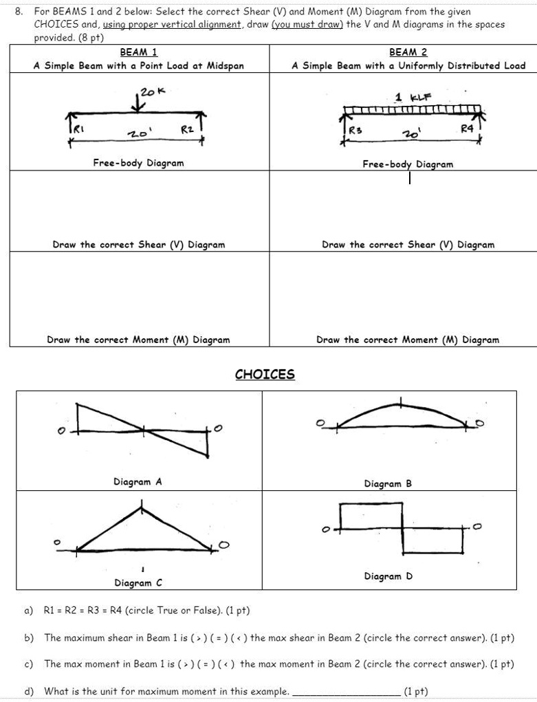
The beam is subject to the loading shown. 1. Choose the correct shear diagram from the column on the left. 2. Choose the correct moment diagram from the column on the right. Note: The moment diagrams on the right do not necessarily correspond to the diagrams on the left. Circle answers from following choices.
Select the correct shear diagram for rectangular beams and one way slabs determine the correct shear diagram of reinforced concrete beams beamguru beam calculator andSelect The Correct Shear Diagram For Beam Figure...
Draw the shear-force and bending-moment diagrams for beam ABC. 88 x 10^6 N. 70 km B) 1. 4 kN/m A B- 3 m 3 m Fig Q5 beam, and then draw the M-diagrambelow the V-diagram. Shear force at point B is the sum of point load and uniform load. Then scroll down to see shear force diagrams, moment diagrams, deflection curves, slope and tabulated results.
Once you have the reactions, draw your Free Body Diagram and Shear Force Diagram underneath the beam. Finally calculating the moments can be done in the following steps: 2. From left to right, make "cuts" before and after each reaction/load. To calculate the bending moment of a beam, we must work in the same way we did for the Shear Force ...
This is an example problem that will show you how to graphically draw a shear and moment diagram for a beam. In general the process goes like this:1) Calcul...
Transcribed image text: 4. (10 Points) Select the correct shear diagram for the beam configuration shown. 2.0 Nim A 3 m 7m A B. In En C. D E I NG E. 다.
Check out http://www.engineer4free.com/structural-analysis for more free structural analysis tutorials. The course covers shear force and bending moment diag...
Transcribed image text: Select the correct shear diagram for the beam. (Figure 1) 2wa Figure < 1 of wa 2wa -2wa Submit Request Answer Figure 1 of 1 > Part B ...
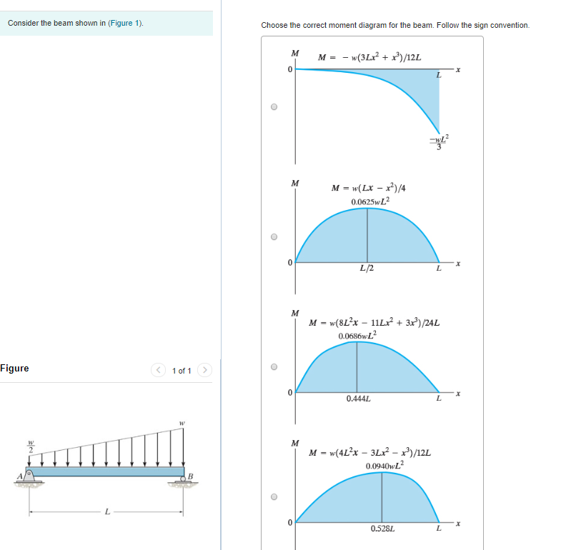
Choose the correct moment diagram for the beam. Follow the sign convention. This problem has been solved! See the answer ...
When the shear diagram is increasing, the moment diagram is concave upward. When the shear diagram is decreasing, the moment diagram is concave downward. Sign Convention The customary sign conventions for shearing force and bending moment are represented by the figures below. A force that tends to bend the beam downward is said to produce a ...
For the beam and loading shown, (a) select the correct shear and bending-moment diagrams, (b) determine the equations of the shear and bending-moment curves. Beam The beam opposes the load applied...
This convention was selected to simplify the analysis of beams. Since a horizontal member is usually analyzed from left to right and positive in the vertical direction is normally taken to be up, the positive shear convention was chosen to be up from the left, and to make all drawings consistent ...
After completing this course… You will be fully competent in drawing shear force and bending moment diagrams for statically determinate beams and frames.; You will have a robust system of analysis that allows you to confidently tackle the analysis of any statically determinate structure.; You will understand the relationship between external loading and the shear forces and bending moments ...
Civil Engineering. Civil Engineering questions and answers. Part A Select the correct shear diagram for the beam. (Figure 1) wa 2a -wa 2wa 2wa x. 2a -2wa wa -Part B Select the correct moment diagram for the beam. 2a 2a 2a 24. Question: Part A Select the correct shear diagram for the beam.
This video explains how to draw shear force diagram and bending moment diagram with easy steps for a simply supported beam loaded with a concentrated load. S...
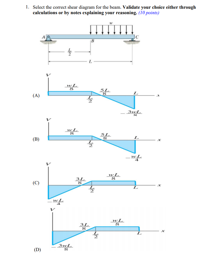
Question: 1. Select the correct shear diagram for the beam. Validate your choice either through calculations or by notes explaining your reasoning. (10 points) ...
E is 2.5 × 10⁴ MPa and the moment of inertia I is 8 × 108 mm4, the correct comparison of the magnitudes of the shear force S and the bending moment M developed at the supports is Q8. A simply supported beam is subjected to a uniformly distributed load.
BEAM DIAGRAMS AND FORMULAS Table 3-23 (continued) Shears, Moments and Deflections 13. BEAM FIXED AT ONE END, SUPPORTED AT OTHER-CONCENTRATED LOAD AT CENTER
Therefore, for continuous moments, the change in moment is related to the integral of the shear load (the area under the shear diagram is related to the change in moment). ... Point loads and point moments: When there is a point load Fo and a point moment Mo applied at a point in the beam, the ...
Transcribed Image Textfrom this Question. Part A Select the correct shear diagram for the beam (Figure 1) V WL * 5L 8 L WL 4 V WL 뿡 X ЗwL. 8 V WL 8 3L 8 WI V wL 8 3L 8 X Figure 3wL 8 Submit Request Answer Part B Select the correct moment diagram for the team.
Select the correct shear diagram for the beam figure 1. This is the end of the preview. Draw the moment diagram for 10 points bonus for the beam shown in the figure below draw the shear diagram. Show all your work bonus points. In the figure below block 1 of mass m 1 slides from rest along a frictionl.
Example solution of shear and moment diagrams of a simple beam using semi-graphical method. Three examples include a single point load, a uniform load, and ...
When drawing the shear force and bending moment diagrams, while the sign convention is important, consistency is crucial. For instance, consider a simple beam loaded with a point load applied on a UD load. Starting the diagrams at support A, looking towards the page, will generate the following:
It is visually desirable to draw the V-diagram below the FBD of the entire beam, and then draw the M-diagrambelow theV-diagram. The bending moment and shear force diagrams of the beam are composites of the Vand Mdiagrams of the segments. These diagrams are usually discontinuous, or have discontinuous slopes.
Answer to part a select the correct shear diagram for the beam. 1 simply supported beam with 2 point loads first of all we need to calculate the reactions or shear force at the supports. Part b identify the m. Calculate the shear force at both supports and show the shear force diagram.
Bendingmomentdiagram offers a range of engineering tools including a FREE Bending moment diagram calculator, Moment of Inertia Calculator and Tutorials!
Describes how to draw shear and moment diagrams graphically for a beam with an overhang.0:30 Calculate Support Reactions2:48 Describe the process for drawing...
a) Calculate the shear force and bending moment for the beam subjected to a concentrated load as shown in the figure. Then, draw the shear force diagram (SFD) and bending moment diagram (BMD). b) If P = 20 kN and L = 6 m, draw the SFD and BMD for the beam. P kN L/2 L/2 A B EXAMPLE 4
Beams -SFD and BMD V = V 0 + (negative of area under the loading curve from x 0 to x) M = M 0 + (area under the shear diagram from x 0 to x) If there is no externally applied moment M 0 at x 0 = 0, total moment at any section equals the area under the shear diagram up to that section When V passes through zero and is a continuous
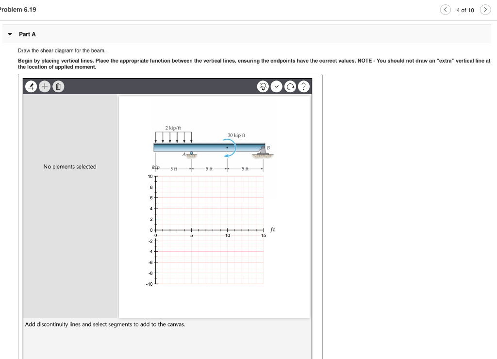
Part A Draw the shear diagram for the beam. Follow the sign convention. (Figure 1) Click on "add vertical line off" to add discontinuity lines. Then click on "add segment" button to add functions between the lines. Note - Make sure you place only one vertical line at places that require a vertical line.
Play this game to review Physics. Select the correct shear force diagram to match this bending moment diagram: Preview this quiz on Quizizz. Select the correct shear force diagram to match this bending moment diagram: ... The beam only has one support at 3m from the left hand side. <p>This is a bending moment diagram.</p> alternatives












0 Response to "42 select the correct shear diagram for the beam."
Post a Comment