44 free body diagram on a ramp
A free-body diagram for a box on a ramp, in the special case of it being the maximum angle before the box starts to slide. The video includes an introduction... Block on ramp: Free-Body Diagram. Author: Nathaniel Cunningham. Free body diagram of a block on a ramp, without friction. Drag the point at the top of the ramp to change the ramp angle. Note how the green angles always track one another.
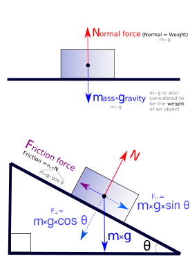
A free body diagram is defined as an illustration that depicts all the forces acting on a body, along with vectors that are applied by it on the immediate environs. Apart from the acting forces and subsequent work done, the moment magnitudes are also considered to be a part of such diagrammatic representations.
Free body diagram on a ramp
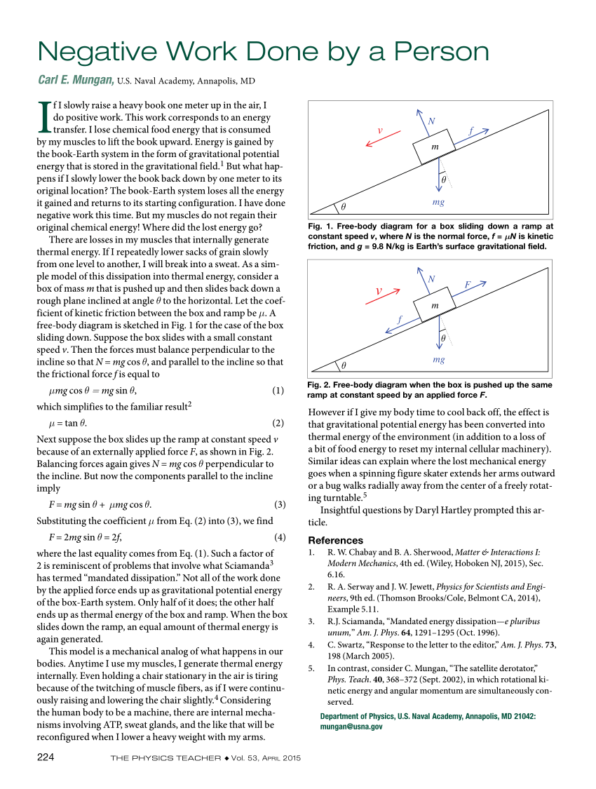
Figure 5.32 (a) The free-body diagram for isolated object A. (b) The free-body diagram for isolated object B. Comparing the two drawings, we see that friction acts in the opposite direction in the two figures. Because object A experiences a force that tends to pull it to the right, friction must act to the left. Because object B experiences a component of its weight that pulls it to the left ... Figure 5.32 (a) The free-body diagram for isolated object A. (b) The free-body diagram for isolated object B. Comparing the two drawings, we see that friction acts in the opposite direction in the two figures. Because object A experiences a force that tends to pull it to the right, friction must act to the left. Because object B experiences a component of its weight that pulls it to the … Figure 5.32 (a) The free-body diagram for isolated object A. (b) The free-body diagram for isolated object B. Comparing the two drawings, we see that friction acts in the opposite direction in the two figures. Because object A experiences a force that tends to pull it to the right, friction must act to the left. Because object B experiences a component of its weight that pulls it to the left ...
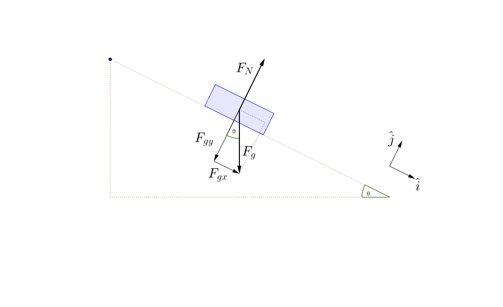
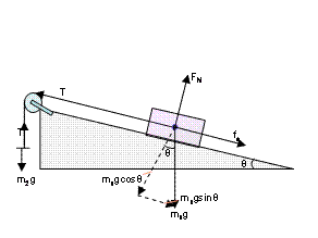
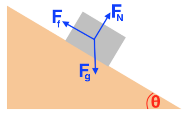
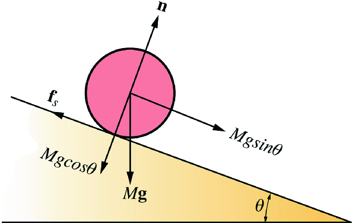
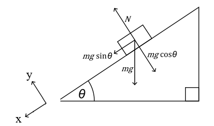
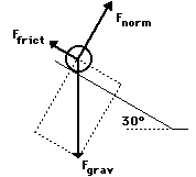
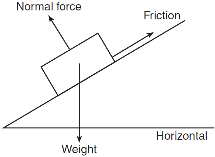
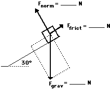
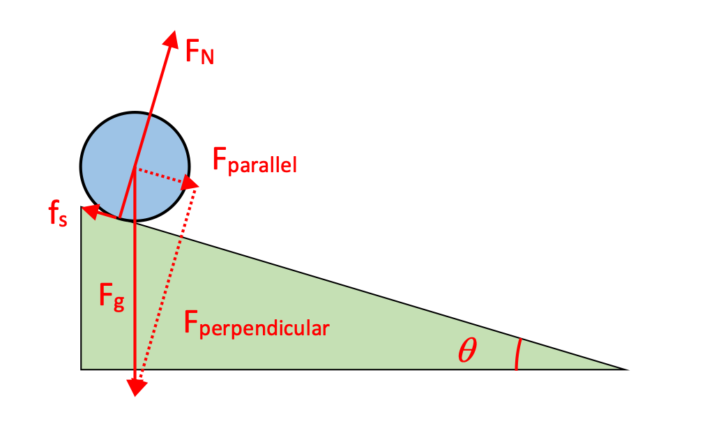
Free body diagram on a ramp. Can you identify the various arrows on the free-body diagram, and figure out which forces are being plotted on the graph as you adjust the angle? Simulation first posted on 10-4-2017. Written by Andrew Duffy. This work by Andrew Duffy is licensed under a Creative Commons Attribution-NonCommercial-ShareAlike 4.0 International License. A free-body diagram is a representation of an object with all the forces that act on it. The external environment (other objects, the floor on which the object sits, etc.), as well as the forces that the object exerts on other objects, are omitted in a free-body diagram. Below you can see an example of a free-body diagram: In this video I explain how to identify the forces acting on a mass that is moving down a ramp. I also explain how to draw these forces on a free body diagra... Free Body Diagram Questions and Answers. Get help with your Free body diagram homework. Access the answers to hundreds of Free body diagram questions that are explained in a way that's easy for ...
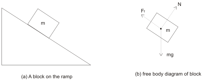
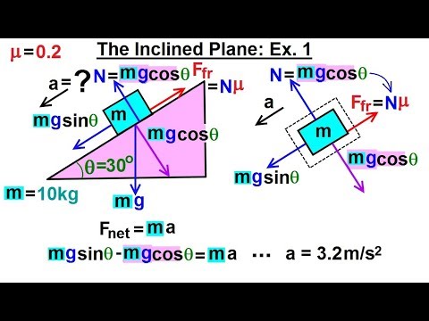
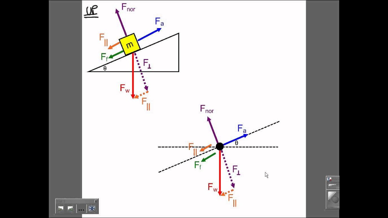
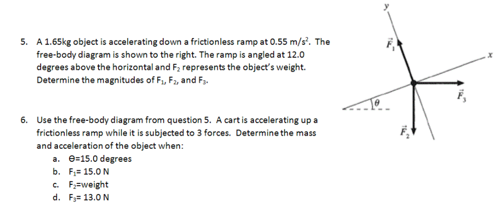
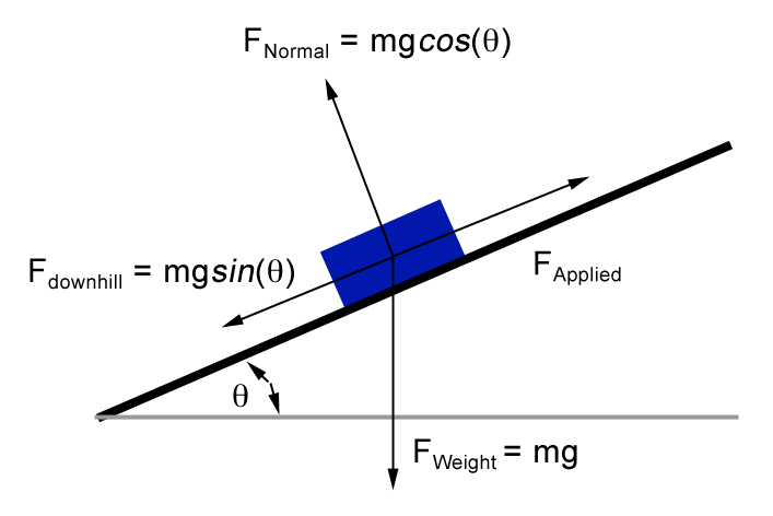
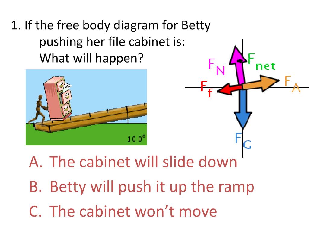
Force Body Diagrams of object sliding down ramp. Ask Question Asked 6 years, 6 months ago. Active 6 years, 6 months ago. Viewed 1k times ... Browse other questions tagged newtonian-mechanics forces free-body-diagram or ask your own question. Featured on Meta Now live: A fully responsive profile ... Q. A box is moving to the left up a ramp. Which way is the force of friction pointing? answer choices . down the ramp to the right. up the ramp to the left ... Q. When completing a free-body diagram, how should you draw the force arrows on the "body"? answer choices . with the arrow tail touching the body. Drawing Free-Body Diagrams. Free-body diagrams are diagrams used to show the relative magnitude and direction of all forces acting upon an object in a given situation. A free-body diagram is a special example of the vector diagrams that were discussed in an earlier unit. These diagrams will be used throughout our study of physics. Let’s apply the problem-solving strategy in drawing a free-body diagram for a sled. In (Figure) (a), a sled is pulled by force P at an angle of 30° 30 °. In part (b), we show a free-body diagram for this situation, as described by steps 1 and 2 of the problem-solving strategy. In part (c), we show all forces in terms of their x – and y ...
An inclined plane, also known as a ramp, is a flat supporting surface tilted at an angle, with one end higher than the other, used as an aid for raising or lowering a load. The inclined plane is one of the six classical simple machines defined by Renaissance scientists. Inclined planes are widely used to move heavy loads over vertical obstacles; examples vary from a ramp used to load … Figure 5.32 (a) The free-body diagram for isolated object A. (b) The free-body diagram for isolated object B. Comparing the two drawings, we see that friction acts in the opposite direction in the two figures. Because object A experiences a force that tends to pull it to the right, friction must act to the left. Because object B experiences a component of its weight that pulls it to the … A free body diagram consists of a diagrammatic representation of a single body or a subsystem of bodies isolated from its surroundings showing all the forces acting on it. In physics and engineering , a free body diagram (force diagram, [1] or FBD) is a graphical illustration used to visualize the applied forces , moments , and resulting ... Work Done on a Box on a Ramp; ... It is correct that only forces should be shown on a free body diagram. However, this is a definition of work problem and not a force problem, so you should draw a picture appropriate for work rather than a free body diagram. Work depends on force, the distance moved, and the angle between force and displacement ...
Figure 5.32 (a) The free-body diagram for isolated object A. (b) The free-body diagram for isolated object B. Comparing the two drawings, we see that friction acts in the opposite direction in the two figures. Because object A experiences a force that tends to pull it to the right, friction must act to the left. Because object B experiences a component of its weight that pulls it to the left ...

Figure 5.32 (a) The free-body diagram for isolated object A. (b) The free-body diagram for isolated object B. Comparing the two drawings, we see that friction acts in the opposite direction in the two figures. Because object A experiences a force that tends to pull it to the right, friction must act to the left. Because object B experiences a component of its weight that pulls it to the …

Figure 5.32 (a) The free-body diagram for isolated object A. (b) The free-body diagram for isolated object B. Comparing the two drawings, we see that friction acts in the opposite direction in the two figures. Because object A experiences a force that tends to pull it to the right, friction must act to the left. Because object B experiences a component of its weight that pulls it to the left ...


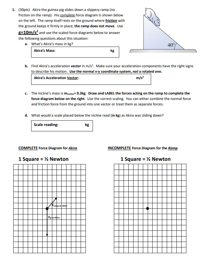


0 Response to "44 free body diagram on a ramp"
Post a Comment