41 intermatic t104 wiring diagram
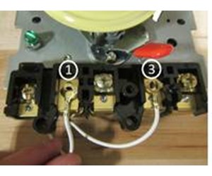
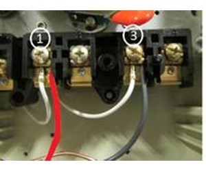
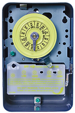
T104 Poles 1 and 3 are 240 source and poles 2 and 4 go to pump motor. I can figure out power - connect t104 pole 1 to pole 2 on GL-235 and pole 3 to pole 3 on GL 235. I don't understand how to wire up poles 5 and 6 on the GL-235 to the T104 controller so that it can auto start pump when it detects freezing weather. Any help would be appreciated. If your timer is 240V, or the T104 model, it will have 5 brass screws (terminals) underneath the plastic insulator cover. Check out the diagram below, or see the wiring diagram which comes with a new timer, or is printed on the door of the timer box.
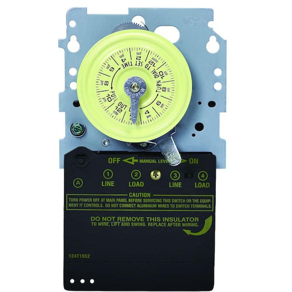
Running pool equipment 24 hours is usually unnecessary and expensive. Installing an Intermatic T104 timer is a great way to dramatically reduce run time and energy costs. The following steps will provide a guide on how to install the T104 timer. Note, timers vary with supply voltage. A T104 timer is used for 230V supply voltage.

Intermatic t104 wiring diagram
Intermatic Timer T104 Wiring Diagram. MAKE SURE WIRE WIRING. DIAGRAM. V 2 WIRE. AND GROUND. LR UL Moving the clock hands can damage the timer. Is clock motor WG? Intermatic T Basic wiring diagram, T timer Volts or Volts Check label on side of water heater for Volts & Watts This timer. T & T are Volt timers; T, T & T are Volt timers. Intermatic T104 Series 40 Amp 208 277 Volt Dpst 24 Hour Mechanical Time Switch Mechanism T104md89 The. Solarattic Solar Pool Heater Wiring Diagrams. Guidance needed for wiring of pool pump timer bypass in 240v system diy home improvement forum intermatic t104 off tripper turns the clock doityourself com community forums with heater delay ... Effectively read a electrical wiring diagram one offers to know how typically the components inside the system operate. It shows the components of the circuit as simplified shapes and the power and signal friends in the midst of the devices. By Vallery Masson on August 2 2021. Get Intermatic Timer T104 Wiring Diagram Sample.
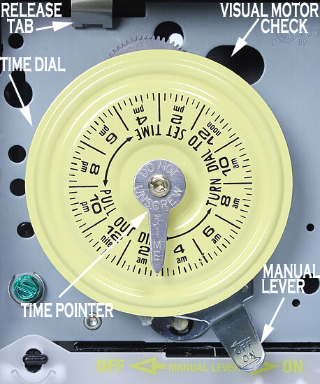
Intermatic t104 wiring diagram. wiring diagram 240 v 2 wire and ground clock motor: 120 vac, 60 hz. clock motor voltage and cycle must be as specified. to order replacement, indicate part no. (wg--) on motor cover. time pointer time dial off tripper manual lever on tripper typical wiring diagram clock motor 120/240 volt 3 wire supply to loads ground line 2 line 1 a 2 4 gr. 1 ... Assortment of intermatic timer t104 wiring diagram. A wiring diagram is a streamlined traditional photographic depiction of an electrical circuit. It reveals the components of the circuit as streamlined forms, and also the power and also signal links between the gadgets. Intermatic T Basic wiring diagram, T timer Volts or Volts Check label on side of water heater for Volts & Watts This timer. The T Series mechanical time switch has proven it can stand the test of time. These dependable time switches can handle electrical loads up to 40 A per. You would wire a T103 for a 220V load as shown in the below pic. Not clearly shown on the pic but the 120V clock motor must be connected between terminal A and terminal 1. Hope this helps. added: btw, I took a look at your pic! Your existing T103 timer is wired correctly and in the same way as shown in the above wiring diagram.
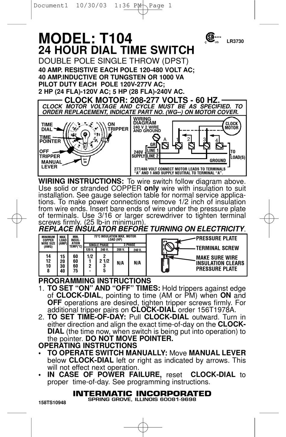
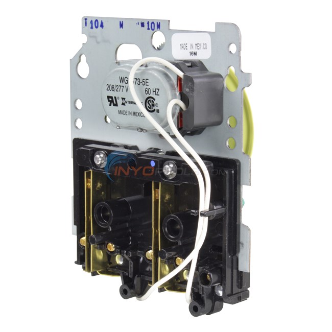
MODEL: T104 24 HOUR DIAL TIME SWITCH DOUBLE POLE SINGLE THROW (DPST) 40 AMP. RESISTIVE EACH POLE 120-480 VOLT AC; 40 AMP.INDUCTIVE OR TUNGSTEN OR 1000 VA PILOT DUTY EACH POLE 120V-277V AC; 2 HP (24 FLA)-120V AC; 5 HP (28 FLA)-240V AC. WIRING INSTRUCTIONS:To wire switch follow diagram above. Use solid or stranded COPPER only wire with insulation ... Get recommended Intermatic products to use when replacing another manufacturer's product. Learn More. ... T104 Instructions. T100 Specifications. 24-Hour Mechanical Time Switch, 208-277 VAC, 60Hz, DPST, Indoor Metal Enclosure, 1 Hour Interval ... Wire Size Max #8 AWG: Wire Size Min #14 AWG: Operating Temperature Max (°C) 54: MODEL: T104 24 HOUR DIAL TIME SWITCH DOUBLE POLE SINGLE THROW (DPST) 40 AMP. RESISTIVE EACH POLE 120-480 VOLT AC; 40 AMP.INDUCTIVE OR TUNGSTEN OR 1000 VA PILOT DUTY EACH POLE 120V-277V AC; 2 HP (24 FLA)-120V AC; 5 HP (28 FLA)-240V AC. WIRING INSTRUCTIONS:To wire switch follow diagram above. Use solid or stranded COPPER only wire with insulation ... Hello Gene, The timer has a number of connection points. Here is a link to the Intermatic Timer Mechanism Only 220V T104 wiring diagram. If you need help installing the timer, we have a How To Install an Intermatic T104 Timer that can provide additional assistance. This timer is for a 220v hook up. Reply ?
Intermatic Timers (T103, T104, T105, T173, T174, T175, T176, T185, WH40), Timer Controls Accessories 4.8 out of 5 stars 306 Trailblazer Wiring Diagram - Complete Wiring Schemas Page 1/3. Download Ebook Intermatic T103 Timer Instructions Symposia. ITMAT symposia enlist outstanding speakers from the US and abroad to address topics Intermatic Incorporated manufactures timer switches designed for indoor and outdoor use. Many pool pump motors and water heaters use Intermatic timers to regulate their run times. An Intermatic timer-switch saves electricity when it turns a water heater off at night and when it limits the amount of time a pool's filtration system runs. New Member. Apr 21, 2009, 01:48 PM. Intermatic T104 wiring (simple terms) I am trying to wire an Intematic timer model #T104 to my pool pump. I have a black wire, a red wire, and a green (ground) wire. To my pump, I have a black, red and green wire. To my salt converter, I have a black, pink and green wire. The key.Jul 18, · T Timer Wiring Diagram intermatic wall timer instructions intermatic wall timer instructions buy now model overview specifications resources digital timer with astro random and dst features 7 on off program events sony hcd ep service manual pdf download view and download sony hcd ep service manual online hcd ep stereo.
How To Wire Connect Intermatic Pool Pump Timer SIMPLE SHORT VIDEO
48+ Intermatic Dt104 Wiring Diagram. Connect the wires to the proper terminals on the time switch and tighten the screws firmly (see wiring diagrams). Use solid or stranded copper only wire with insulation to suit installation. The workhorse of the equipment pad, these timer clocks can .
How To Replace an Intermatic T104 Clock Motor - INYOPools.com
MODEL: T104 24 HOUR DIAL TIME SWITCH DOUBLE POLE SINGLE THROW (DPST) 40 AMP. RESISTIVE EACH POLE 120-480 VOLT AC; 40 AMP.INDUCTIVE OR TUNGSTEN OR 1000 VA PILOT DUTY EACH POLE 120V-277V AC; 2 HP (24 FLA)-120V AC; 5 HP (28 FLA)-240V AC. WIRING INSTRUCTIONS: To wire switch follow diagram above. Use solid or stranded COPPER only wire with ...

T104 Intermatic 40A 208-277V DPST Metal Indoor Time Clock
Assortment of intermatic timer t104 wiring diagram. A wiring diagram is a simplified standard photographic depiction of an electric circuit. It reveals the components of the circuit as streamlined forms, and also the power and also signal connections in between the tools.

How to wire Intermatic T104 and T103 and T101 timers
Intermatic T 104 Wiring Diagram These dependable time switches can handle electrical loads up to 40 A per pole and allow for up to 12 ON/OFF operations per day. A manual override switch. WIRING INSTRUCTIONS: To wire switch follow diagram above. Use solid or stranded COPPER only wire with insulation to suit installation. See gauge selection.
T104 Series 40 Amp 208-277-Volt DPST 24 Hour Mechanical Time Switch Mechanism
Wire Size Max #8 AWG: Wire Size Min #14 AWG: Operating Temperature Max (°C) 54: Operating Temperature Max (°F) 130: Operating Temperature Min (°C)-40: Operating Temperature Min (°F)-40: Product Depth (in) 3 5/8: Product Depth (mm) 92.1: Product Height (in) 10 1/8: Product Height (mm) 257.2: Product Width (in) 6 1/2: Product Width (mm) 165.1 ...

Intermatic 4004 timer
Effectively read a electrical wiring diagram one offers to know how typically the components inside the system operate. It shows the components of the circuit as simplified shapes and the power and signal friends in the midst of the devices. By Vallery Masson on August 2 2021. Get Intermatic Timer T104 Wiring Diagram Sample.

How to wire Intermatic ET series timer
Intermatic T104 Series 40 Amp 208 277 Volt Dpst 24 Hour Mechanical Time Switch Mechanism T104md89 The. Solarattic Solar Pool Heater Wiring Diagrams. Guidance needed for wiring of pool pump timer bypass in 240v system diy home improvement forum intermatic t104 off tripper turns the clock doityourself com community forums with heater delay ...

How to wire Intermatic T104 and T103 and T101 timers
Intermatic Timer T104 Wiring Diagram. MAKE SURE WIRE WIRING. DIAGRAM. V 2 WIRE. AND GROUND. LR UL Moving the clock hands can damage the timer. Is clock motor WG? Intermatic T Basic wiring diagram, T timer Volts or Volts Check label on side of water heater for Volts & Watts This timer. T & T are Volt timers; T, T & T are Volt timers.

How to replace your mechanical time clock

How to wire Intermatic T104 and T103 and T101 timers

SOLVED: Im r\putting in a new timer, i have 120 going in - Fixya

SOLVED: My pool timer has stopped turning the filter pump - Fixya

SOLVED: I want to hook up a new intermatic t103 timer. I - Fixya
Intermatic Pool Timer Troubleshooting - InTheSwim Pool Blog

SOLVED: Intermatic t1202T 240v dual pool timer. Main - Fixya

How to wire Intermatic T104 and T103 and T101 timers

How to wire Intermatic T104 and T103 and T101 timers

Intermatic T104R won't turn pump on, but does turn it off ...
Need help hooking up pool pump to relay switch and Intermatic ...

How To Replace an Intermatic T101M (120V) Pool Timer

Intermatic Pool Timer Troubleshooting - InTheSwim Pool Blog
How to operate and set T104 timer

How to wire Intermatic T10604R control center | Power wire ...

Help with weird pool pump wiring. : r/electricians

Intermatic T104 Electromechanical Timer, 208-277 V, 40 A, 1 ...
How To Install an Intermatic T104 Timer - INYOPools.com
Intermatic Pool Timer Troubleshooting - InTheSwim Pool Blog

I have a new intermatic ET 1125 timer for my pool. Need ...
Intermatic T104 User Manual
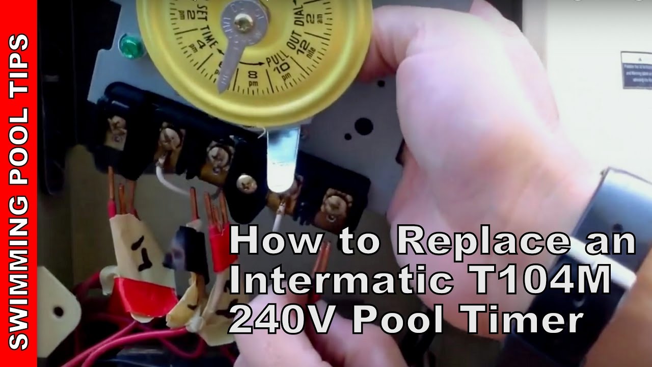
How to Replace an Intermatic T104M 240V (208 277 V) Pool Timer

How to wire Intermatic T104 and T103 and T101 timers

How to wire Intermatic T104 and T103 and T101 timers

How to wire Intermatic T104 and T103 and T101 timers

Intermatic T104 Series 40A 208 277V DPST 24 Hr Mechanical ...

Intermatic T104 Supplementary Manual | Manualzz

How to wire T106 timer

Intermatic T104R won't turn pump on, but does turn it off ...

main | 24-Hour Mechanical Time Switch, 120 VAC, 60Hz, SPST ...
INTERMATIC T104 SWITCH SUPPLEMENTARY MANUAL | ManualsLib

Intermatic T104M Mechanical Time Switch Mechanism Only
Intermatic Timer Mechanism Only 220V - T104M
0 Response to "41 intermatic t104 wiring diagram"
Post a Comment