42 ni cr phase diagram
The (Cr,Ni)Si alloys were found to yield two phases, one high in Ni content and the other low in Ni content. The σ phase existed at high temperatures and was formed directly from the liquid. The Cr... For "normal diagrams", where interested in all . components, use the . Normal equilateral . triangle. For diagrams where there is a major . component, e.g. Fe in Fe-C-Cr, use a . right-angled triangle →
Phase equilibria of the Cr-Ni-C system in the melting (crystallization) range were investigated by means of metallography, microprobe analysis, powder x-ray diffraction, differential thermal analysis, and melting point technique (Pirani and Alterthum method). On the basis of received results and assessment of available literary data, the phase diagram was presented as projections of solidus ...

Ni cr phase diagram
Predictions of the solidification phases in Cr-Ni stainless steel alloys, based on the ratio of the Cr and Ni equivalent, are shown. Incorporating these ratios into the phase solidification diagram helps to predict whether the solidification of a Cr-Ni stainless steel occurs in primary ferritic or austenitic phase. Phase Diagram. このサイトを検索 ... Ni-Cr. Data from RICT-Sol alloy database ver.1.0. Sign in | Recent Site Activity | Report Abuse | Print Page | Powered By Google Sites ... Animation of the Fe-Cr-Ni phasediagram at different temperatures using the Thermo-Calc software.
Ni cr phase diagram. (0.10), Mo (2.5), Ni (11), Cr (18), Fe (68.4). The phase diagram of this material is 5-dimensional, and beyond the scope of this course. The Cu-Ni and binary phase diagram (Figure 10.3) is the simplest type of binary phase diagrams for two metals. Figure 10.3 shows that Cu and Ni are mutually soluble at room temperature throughout the entire range of compositions. In our studies the , γ andα phases exist in Cr-Ni binary phase diagram. The structures of the , γ and α phases belong to A2, A1 and , respectively. predictions for the phase behaviour of multi-component alloys based on models for the binary and ternary phase diagrams. This paper will present a review of results which can now be obtained in alloys from the following multi-component system Ni-Al-Co-Cr-Hf-Mo-Nb-Ta-Ti-W-Zr-B-C Current work involving the extension of the database to Phase diagrams for FE-CR-NI based alloys Part 1: Phase diagrams for binary and ternary alloys of FE, CR and NI with C and with SI Publication metadata
Phase Diagrams All the phase diagrams were calculated by Pandat. Ag Binary Phase Diagrams. Ag-Al Ag-Au Ag-B Ag-Bi Ag-Ca Ag-Ce Ag-Co Ag-Cr Ag-Cu Ag-Dy Ag-Er Ag-Fe Ag-Ga Ag-Gd Ag-Ge Ag-Hf Ag-Hg Ag-Ho Ag-In Ag-Ir Ag-La Ag-Mg Ag-Mo Ag-Na Ag-Nd Ag-Ni Ag-Os Ag-Pb Ag-Pd Ag-Pr Ag-Pt Ag-Rh Ag-Ru Ag-Sb Ag-Sc Ag-Si Ag-Sn Ag-Sr Ag-Tb Ag-Te Ag-Ti Ag-V Ag-W ... nickel, Ni, chromium, Cr, nickel-chromium, Ni-Cr, chromium-nickel, Cr-Ni, nickel-chromium phase diagram, Ni-Cr phase diagram, chromium-nickel phase diagram, Cr-Ni phase diagram, computational thermodynamics, Thermo-Calc, CALPHAD, phase diagram, phase diagrams, metallurgical engineering, metallurgy, materials science, materials engineering, steel, steels, superalloy, superalloys It is evident from Figure 6 (Fe-Cr-C phase diagram) that typical martensitic steels should exhibit ferrite and M 23 C 6 in equilibrium at for example, 600°C. In practice, this carbide is only found after relatively long ageing. because it is preceded by Intermediate phases in the sequence cementite, M 2 X and M 7 C 3, leading finally to M 23 C 6. Isothermal sections of the Ni-Cr-W ternary equilibrium phase diagram were experimentally determined at 1 000 and 1 loo"c. Emphasis was placed upon the nickel-rich corner of the Ni-Cr-W system. Six different alloys with multi-phase compositions were arc-melted in an argon atmosphere from high
The Al-Ni-Cr phase diagram was specified at 1000 °C and partially at 900 °C. The results concerning the region below 60 at.%. Al agreed qualitatively with the literature data. The binary Al-Cr phases μ and γ dissolve up to ∼1 and ∼3 at.%. Ni, respectively, and Al 3 Ni 2 up to ∼2.5 at.%. Phase diagrams at intermediate temperatures are critical both for alloy design and for improving the reliability of thermodynamic databases. There is a significant shortage of experimental data for phase diagrams at the intermediate temperatures which are defined as around half of the homologous melting point (in Kelvin). The goal of this study is to test a novel dual-anneal diffusion multiple ... File:Diagramme phase Fe Cr Ni.svg. Size of this PNG preview of this SVG file: 638 × 438 pixels. Other resolutions: 320 × 220 pixels | 640 × 439 pixels | 1,024 × 703 pixels | 1,280 × 879 pixels | 2,560 × 1,757 pixels. The Ni-Co-Cr phase diagram is characterized by a large σ phase region over a wide temperature range and extends from the Co-Cr binary towards the Ni-Cr binary. The phase boundary of the fcc phase determined by Omori et al. is consistent with that measured by Jin and Rideout et al. .
Ternary diagram for the Fe-Cr-Ni system at 400°C ...
Al-Cr-Ni_1273K FSstel: Al-Cr-O_Al-Cr-O2_P(O2)=air FToxid: Al-Cr-O_Al2O3-CrO-Cr_a(Cr)=1 FToxid: Al-Cr-O-Si_Al2O3-SiO2-CrO-Cr_1400C_a(Cr)=1 FToxid: Al-Cr-O-Si_AlO1_5-CrO1_5-O2-SiO2_P(O2)_1600C FToxid: Al-Cr-O-Si_AlO1_5-CrO1_5-O2-SiO2_P(O2)_1700C FToxid. Al-Cr-O-Si_AlO1_5-CrO1_5-O2-SiO2_P(O2)_1800C FToxid: Al-Cr-O-Si_AlO1_5-CrO1_5-O2-SiO2_P(O2)_1900C FToxid

Fe-Cr Phase Diagram | Diagrama
SGTE - SGTE 2017 Alloy Phase Diagrams (1176) Click on a system to display the phase diagram. Ag-Al. Ag-Au. Ag-Au-Bi_1000K. Ag-Au-Bi_500K. Ag-Au-Bi_liq. Ag-Au-Sb_1000K. Ag-Au-Sb_500K.

Cr-Fe-Ni Phase Diagram | Science & Engineering | Pinterest
by P Nash · 1986 · Cited by 113 — Voss, “The Chromium-Nickel Alloys,”Z. Anorg. Chem., 57, 58–61 (1908) in Germn. (Equi Diagram, Crys Structure; Experimental; Indicates presence of a phase ...

red bmw m 3 parked on street
Cr-Ni Phase Diagram [2006Tur] Modeling of Ni-Cr-Mo based alloys: Part I - Phase stability, P.Turchi, L.Kaufman, Z.-K.Liu, CALPHAD, 30 (2006) 70-87. Database for FactSage (registration required) [2006Cha] Computation of Ni-Cr phase diagram via a combined first-principles quantum mechanical and Calphad approach,

IN718 nickel-based superalloy held for 24 hours at 850°C
File:Fe-Cr-Ni-solidus-phase-diagram.svg. Size of this PNG preview of this SVG file: 400 × 400 pixels. Other resolutions: 240 × 240 pixels | 480 × 480 pixels | 600 × 600 pixels | 768 × 768 pixels | 1,024 × 1,024 pixels | 2,048 × 2,048 pixels.

Fe-Ni-Cr pseudo-binary phase diagram. | Download ...
Approximate phase diagrams of the Al-Co-Cr-Fe-Mo-Ni HEA system were constructed for the various contents of each composing element, based on SEM, XRD, HTXRD, and DTA analyses. These diagrams could be helpful in understanding the alloy system and could further the field of alloy design and development.

Phase diagram of the pure binary Cr-Ni system with ...
To account for the stability of the Ni 2 Cr phase and the hypothetical Ni 2 Mo and Ni 2 W phases, available thermodynamic data and ab initio electronic structure-based results were employed. A comparative study of property diagrams for the nominal composition of several YMP candidate alloys is presented.

Ni-Cr phase diagram. Compositions of alloys studied are ...
FESEM micrograph showing the quaternary eutectic of Ni-rich boride (Ni 3 B), Cr-rich boride (CrB), Ni-rich borosilicide (Ni 6 Si 2 B) and eutectic-γ (γ E ) solid solution: (a,b)overall overview ...

Co-Cr - Phase Diagram
Temperature-composition diagram Binary phase diagram of Pb-Sn 1.1. Definition and experimental determination of an equilibrium phase diagram X A = n A / N-n A and n B: number of moles of A and B; m A and m B mass of A and B;-N = n A + n B: total mole number ; M = m A + m B: total mass; X A and X B mole fractions of A and B: X B= n B / N w A = m A / M w A and w

IN718 nickel-based superalloy held for 72 hours at 850°C
Sep 01, 2015 · The Ni-Cr-Ru phase diagram is essential to understand the Ru effect on superalloys. • Diffusion multiples are employed to obtain four Ni-Cr-Ru isothermal sections. • A new Cr-Ru binary phase diagram is suggested based on new experimental data. • CALPHAD assessments are performed to obtain the thermodynamic parameters.

Isothermal section at 1523 K of the Fe-Nb-Ni ternary phase ...
Phase diagram available to subscribers; ... End Points: Cr 9.4 Ni 6.7 Ti 83.9-Ni 6.6 Ti 93.4; Concentration Range: T[500-1000 °C] vs. Cr conc.[0-10 wt ...

Fe-Ni-Cr Phase Diagram | Science & Engineering | Pinterest ...
by Y Ustinovshikov · 2012 · Cited by 26 — Grains of the Cr 2 Ni chemical compound (orthorhombic lattice) are formed in ... TEM method doesn't do not completely coincide with the Ni–Cr phase diagram.

Ni-Superalloy, exposed microstructure
Effect of Alloying elements in Steel, TTT diagram and Phase transformation diagram Metals , Steel Literature / March 30, 2020 September 14, 2021 It's a long-standing tradition to discuss the effect of alloying elements in steel to achieve better properties like Nickel make steel tougher and chromium makes steel harder.

The pseudo-binary phase diagram on the vertical section of ...
Phase diagramis a graphical representation of all the equilibrium phases as a function of temperature, pressure, and composition. For one component systems, the equilibrium state of the system is defined by two independent parameters (P and T), (T and V), or (P and V). Phase diagram Pressure-temperature phase diagram for H2O:

(PDF) Precipitation of Phase Using General Diffusion ...
Ni Fe + Cr Nb + MO + Si Figure 3. Psuedo-Equilibrium Ternary Solidification Diagram for A718 Showing Solidification Path Direction from y to y t A,B Laves Phase (After Reference 5) Figure 3 also indicates that higher levels of Nb, MO, and Si promote the formation of Laves phase.

Ni-P - Phase Diagram
The solid-state phase diagram of Cr-Ni consists of three main phases: fcc and bcc solid solutions and the CrNi 2 intermetallic compound. Previous thermodynamic assessments of Cr-Ni have been...

person in blue jacket walking on green grass field during daytime
The thermodynamic data are incorporated into an existing database for Ni alloys and used in conjunction with the CALPHAD approach to compute the binary Ni-Cr phase diagram. In addition, a thermodynamic model is used to treat long-range ordering and the formation of the Ni 2 Cr. The phase field for ordering is compared against that predicted by the Thermo-Calc to elucidate possible implications on the long-term phase stability of Ni-base alloys in a nuclear waste repository environment.

Calculated isothermal sections of the Ni-Cr-Mo phase ...
For convenience in all diagrams the boundary of phase regions containing BCC-A2 in various equilibria is represented as bold black line. We highlighted this boundary because in wide parts it corresponds to the binodal line leading to spinodal decomposition of BCC-B2 into Fe, Cr-rich and Al, Ni-rich phases.

DSC02145
A hypothetical ternary phase space diagram made up of metals . A, B, and . C. is shown in Fig. 10.2. This diagram contains two binary eutectics on the two visible faces of the diagram, and a third binary eutectic between ele-ments . B. and . C. hidden on the back of the plot. Because it is difficult to use . Fig. 10.1 . Space model for ternary phase diagrams. Fig. 10.2

yellow petaled flower close-up photography
Animation of the Fe-Cr-Ni phasediagram at different temperatures using the Thermo-Calc software.

Fe-Cr-Ni phase diagram for 70 wt.% Fe. The shaded area ...
Phase Diagram. このサイトを検索 ... Ni-Cr. Data from RICT-Sol alloy database ver.1.0. Sign in | Recent Site Activity | Report Abuse | Print Page | Powered By Google Sites ...

Ni-N - Phase Diagram
Predictions of the solidification phases in Cr-Ni stainless steel alloys, based on the ratio of the Cr and Ni equivalent, are shown. Incorporating these ratios into the phase solidification diagram helps to predict whether the solidification of a Cr-Ni stainless steel occurs in primary ferritic or austenitic phase.

Ni-Cr - Phase Diagram

Metastable phase diagram showing the effect of Cr and Ni ...

IN718 nickel-based superalloy held for 1 minute at 850°C

Fe-Mn - Phase Diagram
![Cu-Ni phase diagram [2]. | Download Scientific Diagram](https://www.researchgate.net/profile/Andras_Kovacs13/publication/321224714/figure/download/fig1/AS:631621728337962@1527601763764/Cu-Ni-phase-diagram-2.png)
Cu-Ni phase diagram [2]. | Download Scientific Diagram

The alloy compositions selected in binary Ni-Zr phase ...

Vertical Section of the Fe-Cr-Ni Phase Diagram at 70% Fe ...

Fe-Cr - Phase Diagram
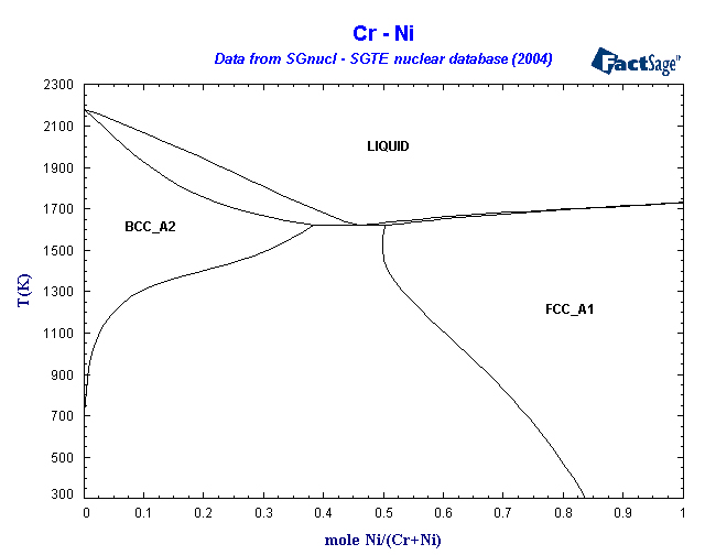
SGnucl - SGTE Nuclear Phase Diagrams

Cu-Ni - Phase Diagram
![Results of optimized calculation [45] of phase diagram of ...](https://www.researchgate.net/profile/Alexander_Udovsky/publication/260795798/figure/download/fig2/AS:642108276879361@1530101951276/Results-of-optimized-calculation-45-of-phase-diagram-of-the-Ni-Cr-system.png)
Results of optimized calculation [45] of phase diagram of ...

Nickel-Chromium (Ni-Cr) Phase Diagram | Science ...

unknown

Calculated isothermal sections of the Ni-Cr-Mo phase ...

Calculated Ni-Cr phase diagram as obtained in the present ...

Evolution of Microstructure and Residual Stress under ...
Fe-Cr binary phase diagram adapted from Massalski see Ref ...
brown concrete building

Phase diagram of the pure binary Cr-Ni system with ...

2 Phase diagram of a bulk Fe-V alloy system [36 ...
0 Response to "42 ni cr phase diagram"
Post a Comment