40 High Pass Filter Diagram
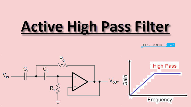
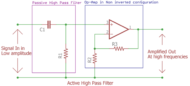
Low Pass & High Pass Filter Working Principle - Electrical ... The opposite to the low-pass filter is the high-pass filter. High-pass filters pass chosen high-frequency current and reject low-frequency currents. The filter ... High Pass Filter Diagram - U Wiring Oct 03, 2021 · Above this cut-off frequency point the reactance of the capacitor has reduced sufficiently as to now act more like a short circuit allowing all of the input signal to pass. High pass filter diagram. Wide variety including LTCC ceramic reflectionless lumped and suspended substrate. The frequency response of the circuit is the same as that of the passive filter except that the amplitude of the signal is increased by the gain of the amplifier.
High Pass Filter- Explained - Learning about Electronics This circuit will form a high pass filter, passing through high frequency signals through to output, while filtering low-frequency signals through the inductor. Since the formula for a high-pass RL filter is f= R/2πL, doing the math we get, f= R/2πL= 10KΩ/ (2 (3.14) (470mH))= 3,388 Hz, which is approximately 3.39KHz.

High pass filter diagram
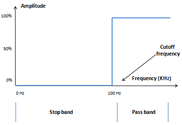
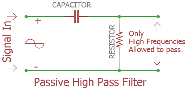
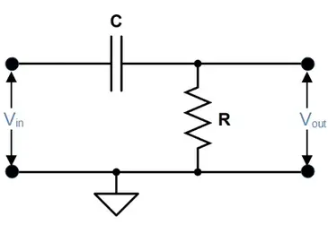
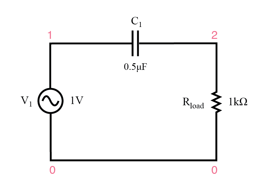
High-pass filter - Wikipedia A high-pass filter (HPF) is an electronic filter that passes signals with a frequency higher than a certain cutoff frequency and attenuates signals with ... High Pass Filter: Circuit, Transfer Function & Bode Plot ... Jan 13, 2020 · The RC filter is one type of passive filter because it consists only of a capacitor is in series with the resistor. The circuit diagram of high pass and low pass filter is the same, just interchange the capacitor and resistor. The circuit diagram of the RC high pass filter is as shown in the below figure. High-pass Filters | Filters | Electronics Textbook - All About ... As with low-pass filters, high-pass filters have a rated cutoff frequency, above which the output voltage increases above 70.7% of the input voltage. Just as in ...
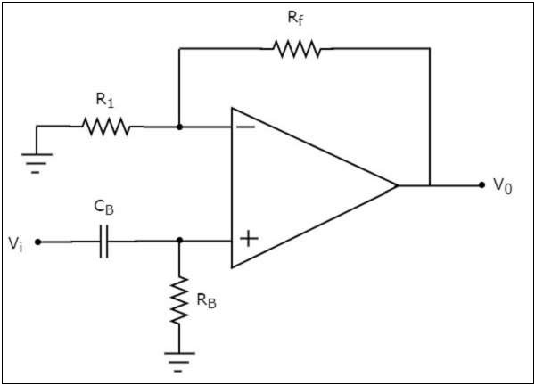
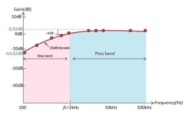
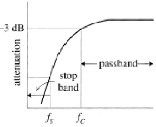
High pass filter diagram. High Pass Filter : Circuit, Characteristics and Its Applications Aug 7, 2020 — It is also known as a flat-flat filter, used in various applications where the closed-loop gain of the passband is unity. The circuit diagram ... High Pass Filter - Electronics Reference High Pass Filter Circuit Diagram A high pass filter consists of a capacitor and resistor in series. The input waveform V in is passed through the capacitor, and the output waveform V out is measured across the resistor. High Pass Filter: Definition, Circuit, Characteristics, and ... Gain (dB) = 20 log (Vout/Vin) The slope of high pass filter curve is +20 d B/ decade .i.e. after passing cutoff frequency level the output response of the circuit increases from 0 to Vin at a rate of +20 dB per decade which is 6 dB increase per octave. High Pass Filter Frequency Response. High Pass Filter - Passive RC Filter Tutorial The High Pass Filter Circuit. In this circuit arrangement, the reactance of the capacitor is very high at low frequencies so the capacitor acts like an open circuit and blocks any input signals at VIN until the cut-off frequency point ( ƒC ) is reached. Above this cut-off frequency point the reactance of the capacitor has reduced sufficiently as to now act more like a short circuit allowing all of the input signal to pass directly to the output as shown below in the filters response curve.
High-pass Filters | Filters | Electronics Textbook - All About ... As with low-pass filters, high-pass filters have a rated cutoff frequency, above which the output voltage increases above 70.7% of the input voltage. Just as in ... High Pass Filter: Circuit, Transfer Function & Bode Plot ... Jan 13, 2020 · The RC filter is one type of passive filter because it consists only of a capacitor is in series with the resistor. The circuit diagram of high pass and low pass filter is the same, just interchange the capacitor and resistor. The circuit diagram of the RC high pass filter is as shown in the below figure. High-pass filter - Wikipedia A high-pass filter (HPF) is an electronic filter that passes signals with a frequency higher than a certain cutoff frequency and attenuates signals with ...






![RL High-Pass Filter Circuit [7]. | Download Scientific Diagram](https://www.researchgate.net/profile/Lawrence-Paulson/publication/228832913/figure/fig2/AS:669275413049359@1536579101564/RL-High-Pass-Filter-Circuit-7.png)







0 Response to "40 High Pass Filter Diagram"
Post a Comment