44 4 in 1 esc wiring diagram
XRotor Micro 4-in-1 60A ESC 6S BLHeli_32 - brainfpv 4-in-1 ESC; XT60 connector with 14AWG wires (130mm long) for battery connection; 560uF / 35V capacitor (pre-installed) Pigtail wires. Use the long wire included with the 4-in-1 ESC to connect it to the RADIX FC with red and black wires removed on the RADIX FC side. Leaving the wires connected will damage the RADIX FC! oscarliang.com › build-racing-drone-fpv-How to build a Racing Drone Tutorial (2019 ... - Oscar Liang Apr 05, 2019 · However, I’m confused with the wiring diagram for the Omnibus F4 AIO and FrSky XSR. The XSR has 5 wires, one being a white wire. The white wire doesn’t appear on the diagram, unless it can’t be seen due to the white background. I’ve searched the web for any clues, but can’t find the answer.
Ori32 4in1 Esc Wiring Diagram - schematron.org on Ori32 4in1 Esc Wiring Diagram. Shop 4in1 on Phaser FPV. TBS & Whitenoise X RACE WIRE PCB For 4in1 ESC & AIO FCs SPEDIX GS40 32BIT 4IN1 40A 6S BLHELI32 ESC .. Use the correct wiring diagram from schematron.org Note: When using a Millivolt V2 , . Airbot Ori32 BLHeli32 25A 4-in-1 20x20 ESC (Includes breakout cables). 1.

4 in 1 esc wiring diagram
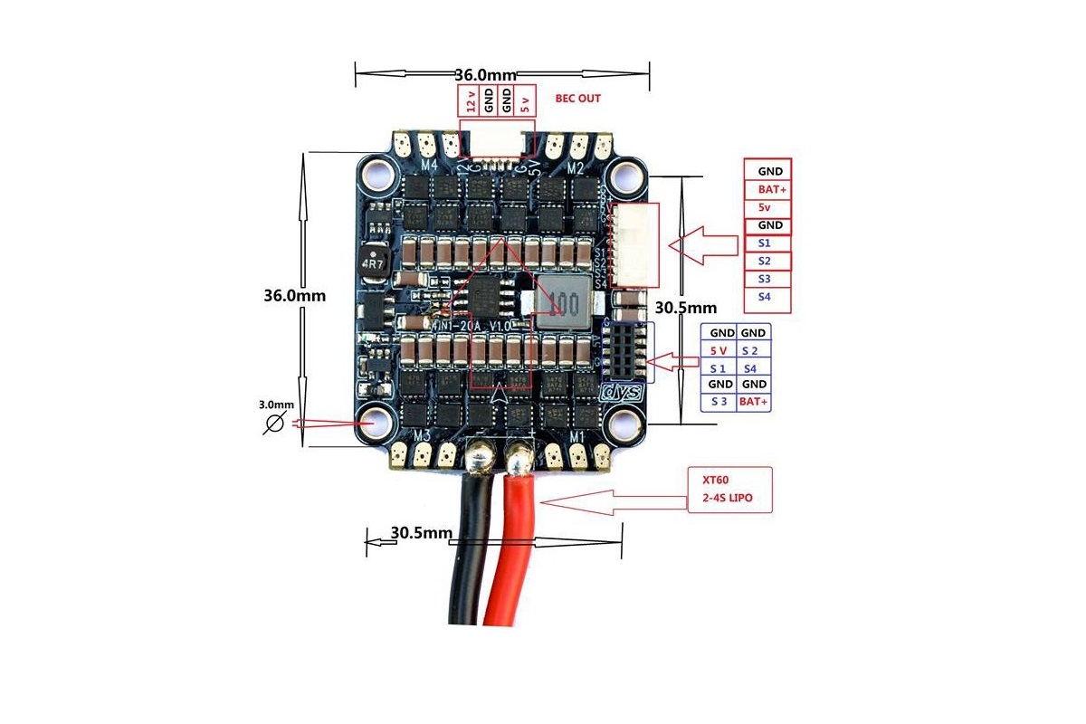
SucceX-E 45A 2-6S BLHeli_S Dshot600 4-in-1 ESC ESC // SucceX-E 45A 2-6S BLHeli_S 4-in-1 ESC. - Dimension: 40*43mm. - Mounting Holes: 30.5*30.5mm/Φ3mm. - Weight: 14.4g. - Supports 2-6S Lipo input. - EFM8BB21 MCU, 24Mhz Runs BLHELI 16.X Firmware. - Current sensor: YES. Xrotor 20x20 stack 4in1 ESC for FPV pilots - HOBBYWING ... Meet XROTOR "FPV" Series - 20x20 4 in 1 stack ESC Model 20x20 Stack 40A 20x20 stack Nano (20A) SKU 30902045 30901068 BLHeli_32 DShot1200 BLHeli-S DShot600 Application 130-300mm FPVsDiagonal Wheelbase 130-280mm FPVsDiagonal Wheelbase Firmware HobbywingXRotor_BLHeli32 BLHeli-S A-H-50 16.5 LiPo Power input 3-6S Lipo 2-4S 4 In 1 Esc Wiring Diagram - easywiring 4 in 1 esc wiring diagram. A 4in1 esc is more convenient to use as there is less messy wiring as the powering of each esc is done internally on the board. Connect the esc for motor 1 to the pdb pins marked m1 motor 6 s esc to the pins marked m6 etc. If have any questions about drone wiring diagram please contact.
4 in 1 esc wiring diagram. XILO Stax Combo - F4 Flight Controller + 4in1 45A BLHeli ... XILO Stax Combo - F4 Flight Controller + 45A BLHeli_32 6s 4-in-1 ESC. The Stax Combo by XILO is a high performance F4 Flight Controller paired with a 45A 32bit 6s 4-in-1 ESC. The plug and play connection makes it easy to install and use on your favorite airframe. Spacing for receiver pins (XM+/Crossfire Nano) is now correct! 4 In 1 ESC - HGLRC Company 4 In 1 ESC. Filter Filter. Best selling Sort by. Sort by. Featured Best selling Alphabetically, A-Z Alphabetically, Z-A Price, low to high Price, high to low Date, old to new Date, new to old. HGLRC Zeus 60A 3-6S BLHeli 32 4in1 ESC for FPV Racing Drone $75.99 - $81.99. › quadcopter-wiring-diagramQuadcopter wiring diagram guide - Rcdronegood.com May 23, 2017 · Connect the ESC for motor 1 to the PDB pins marked M1, motor 6’s ESC to the pins marked M6, etc. This is an example about Esc and motor connect diagram, which is very detailed to show you that how to connect them. Review: Aikon AK32 4in1 35A ESC - Oscar Liang The AK32 4in1 35A ESC is the latest 4-in-1 ESC from Aikon that runs BLHeli_32 firmware. Further Reading: How to choose ESC for Racing Drones? I am quite excited about this 4-in-1 about it's one of the very few BLHeli_32 ESC's that supports up to 6S LiPo batteries.
RUSHFPV RUSH Matrix 30A BLHeli32 4-in-1 ESC - English Backorder. $52.99. The RUSHFPV RUSH Matrix 30A 4-in-1 ESC brings serious power in a 20x20 game. Stackable with other mini FC's like the RUSH CORE 7 Flight Controller and a perfect replacement part or spare part to the RUSH 20X20 Mini Stack . Great specs in a tiny package! HOBBYWING XRotor User Manual - HOBBYWING North America Step 1: Motor Wiring. Step 2: Radio Calibration Turn on the transmitter, move the throttle stick to the top position. Connect the receiver to the battery, ensure the transmitter and receiver are well bound, and then turn on the ESC. After the motor emits two short "beep-beep", move the throttle stick to the bottom position in 3 seconds. Does 4in1 esc orientation matter : multicopterbuilds FC / ESC: T-Motor Mini F7 Stack + F45A 3-6S BLHeli_32 4-in-1 ESC. Battery: 6S. Camera: Caddx Vista. Rx: Crossfire Nano Rx. Controller: Tango 2. Goggles: DJI goggles V2. Motors: T-Motor VELOX V2 V2207 2550KV. See wiring diagram for details. I'm going to pull the 2 left-most cables out of the harness that came with the Caddx vista. Hobbywing Xrotor Smart Audio Wiring Diagram FC/ESC Combo - Hobbywing XRotor Micro V2 Combo: F4 G2 FC and 45A BlHeli_32 4-in-1 Sever the excess wire with the wire cutters and strip the insulation with a penknife or a pair of wire strippers. Be sure to tin each wire before soldering it on to the 4-in - VTX 'Smart Audio' to FC 'UART6-Tx'. Omnibus F4 - Smart Audio with Unify Pro VTX.
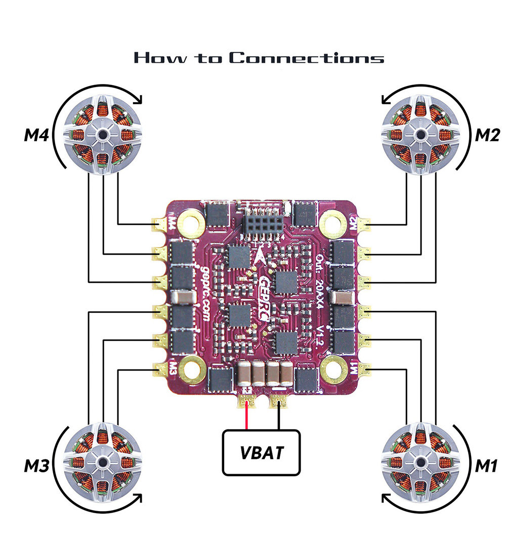
How To Connect Quadcopter Motors and ESC - DroneTrest Typical connections on a 4in1 ESC As you can see in the diagram above for a typhoon ESC, there are 4 groups of 3 motor soldering tabs, so you would solder each motor to each group. To connect the ESC to your flight controller, most 4in1 ESC uses a connector to make wiring neater. Controller F411-WING – Matek Systems STM32F411, MPU6000, INAVOSD, BMP280, 2x UARTs, 1x Softserial, 1x I2C, 2x Motors & 5x Servos, 2x BEC & current sensor on board. PDF 4in1 ESC 45A - FETtec Signal 1 - 4 have to be connected to the corresponding FC Motor outputs. The TLM wire has to be connected to an available serial TX pin. Configuration In order to utilize ESC provided current and voltage sensor the following settings need to be applied to Betaflight. (Feature, motor protocol and meter can be configured through the GUI itself). Racerstar 35a 4 In 1 Esc Wiring Diagram Racerstar has released this ESC for their 11th Anniversary. Equipped with BLheli_S, Dshot, PWM/OneShot/MultiShot, and a current sensor, this 4-in-1 ESC. BLHeli_S 4-in-1 ESC User Manual. 1. Product Features: -Adopted EFM8BB21F16 chip, 50MHz performance frequency. -Designed for superior performance in. Wiring anniversary special edition racestar rev35a Anniversary Special Edition Racerstar REV35 35A BLheli_S S 4 In 1 ESC.
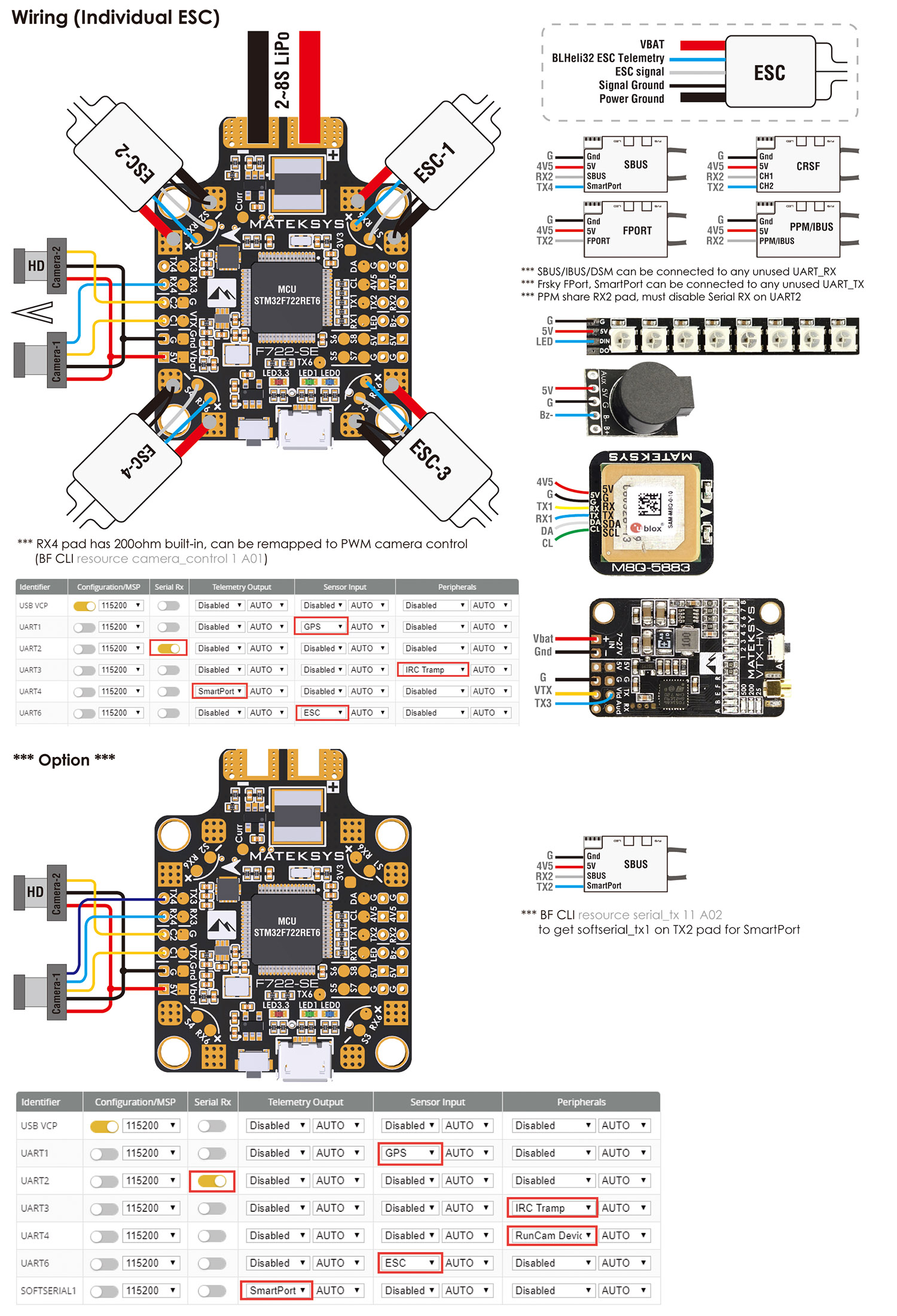
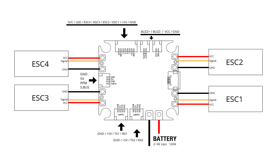
EOL)Flight Controller F722-SE – Matek Systems
4 in 1 ESC Wiring & Set Up - YouTube

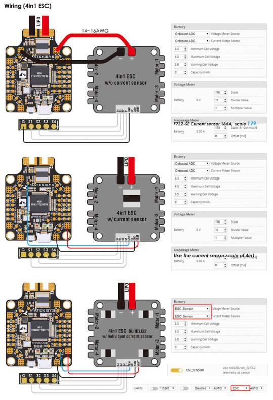
How to setup BLHeli32 ESC Telemetry & Current Sensor - Oscar ...
SucceX 50A 2-6S BLHeli_32 Dshot600 4-in-1 ESC Wiring Diagram; Reviews (5) Product Description. SucceX 50A 2-6S BLHeli_32 Dshot 600 4-in-1 ESC. Features: - 8 layers double-sided PCB board; - 4oz 1.6mm thick power board(0.9mm copper ratio),better operating load capacity; - 32bit G071 MCU, 48mHz maximum clock speed;
HGLRC Omnibus F438, 33A 4 in 1 ESC & Switchable vTx Stack
How to wire a 4 in 1 ESC - YouTube Today I hope to clear up any confusion I have created in wiring a 4 in 1 ESC to your motors and flight controller. All the stuffs I useTranis X9D Plus http:/...

HAKRC 30-amp 4-in-1 BLHeli_S ESC 👍
Drone Wiring Confusion (4in1 esc with a Pixhawk 4) - RC Groups Drone Wiring Confusion (4in1 esc with a Pixhawk 4) Hello there, I'm a 1st time drone builder and am having some troubles getting my head around all of the wiring. The above picture is a picture of my schematics for the whole drone. As you can see in the bottom right, I have not yet shown the wires connecting the (4in1) esc to the pixhawk 4 as I ...

Wiring an external ESC to an AIO Flight Controller if one ESC ...
ardupilot.org › copter › docsConnect ESCs and Motors — Copter documentation The Pixhawk should work with every ESC that works with a normal RC receiver (because it sends the same type of signal) but there is one known exception, the EMAX ESC. In most cases problems are due to incorrect wiring. Always connect signal and ground. Check your ESC type to decide how to connect the +5V line.

4in1 esc with aio fc
All-in-one FC/PDB and 4-in-1 ESC wiring -- series or ... Wire the the battery lead to the 4 in 1 ESC and run thinner wires from the main + and - pads on the ESC to power the fc. Then only run signal wires (plus the one signal ground) to the ESC signal pads on the fc no need to mess with the motor + and - pads on the fc. Hope that makes sense! level 2.
GEPRC Stable F4 MiniTower Omnibus F4 az ESC VTX-vel
ESC wiring and connections - KISS documentation KISS ESC 25A 4-in-1 wiring Wiring Diagram 1. BLDC Motor phases (3) 2. Lipo Power Supply + 3. Lipo Power Supply - (GND) 4. 6-Pin JST connector - for direct connect to KISS FC 5. ESC signal solder pads *1,2,3,4 - in light blue color is the numbering of ESC's Top view Previous Technical data Next FW revisions Last modified 3yr ago

Aikon SEFM 4-in-1 ESC
Wiring diagram - IntoFPV Forum Assuming you mean the T-Motor F55A Pro 4-in-1 ESC, using the white 10-pin and 8-pin ESC connectors on each board respectively, wire it in the following way. You can of course just solder directly to the pads with the same labels on the LUX F7 instead of using the white 8-pin connector if that is going to be easier.

Zeez RC 45A BLHeli_32 4-In-1 ESC V2 – defianceRC
RACERSTAR Official Website Racerstar Crazybee F3 Flight Controller 4 IN 1 5A 1S Blheli_S ESC Compatible Frsky D8 Receiver. 20x20mm Racerstar TaiChi Round Stack F4 OSD 2-6S Flight Controller AIO BEC & 40A BL_32 4in1 ESC for RC Drone FPV Racing.

How To Connect Quadcopter Motors and ESC
› - › mediaWIRING DIAGRAM INDEX - Volvo Trucks 1 (2) 1 (106) wiring diagram index name description page aa power distribution frc 3 ab power distribution frc 4 ac power supply, circuit protection 3/4 (ef 5 ad power supply, circuit protection 4/4 (ef 6 ae grounding 7
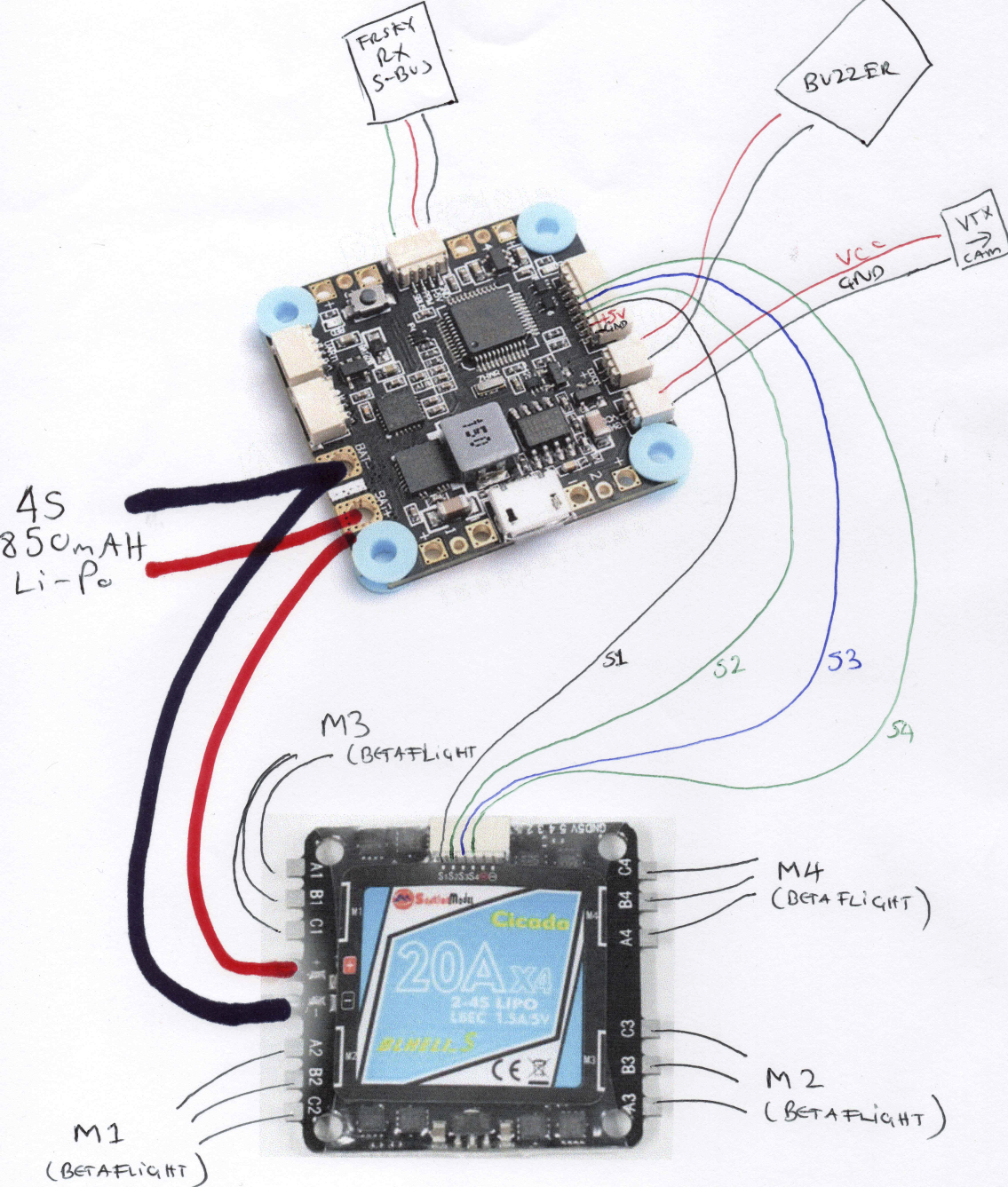
Wiring Cicada 4 in 1 ESC to Diatone FC with integrated PDB ...
flipsky.net › collections › electronic-productsFLIPSKY electric speed controller DIY electric skateboard ESC ... Programmable , efficient and effective electric speed controller ESC for DIY electric skateboards, golf carts, smart cars, robots, multi-axis aircraft etc. Compatible with VESC software, with Flipsky ESC, you have taken the biggest step to bring stronger power to your electric skate board and other electric vehicles.

T-Motor VELOX V50A 3-6S BLHeli_32 4-in-1 ESC
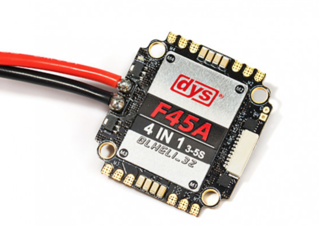
T-Motor F45A 3-6S BLHeli_32 4-in-1 ESC - GetFPV This 4-in-1 ESC packs 45A into an industrialized PCB layout made with premium features such as a 32bit main control chip, BLHeli_32 firmware, and 6s support. The F45A 4-in-1 comes with a heatsink attached to keep heat away from sensitive electronics. Another small bonus is the 4 x motor wire PCBs that come with this ESC.
Wiring a Matek F405 to DYS Aria D45A 4 in 1 ESC – flyingsquirrel
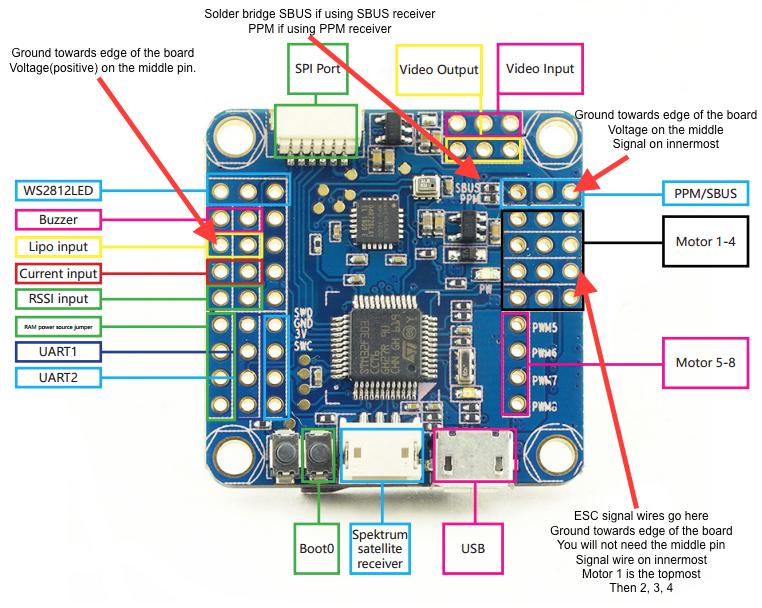
(EOL)Flight Controller F722-SE – Matek Systems 1x I2C. 4x RX6 pad (one per cornet) for BLheli32 ESC telemetry. 4x individual ESC power/signal pads. 1x Group of G/S1/S2/S3/S4 pads for 4in1 ESC Signal/GND. 3x LEDs for FC STATUS (Blue, Green) and 3.3V indicator (Red) Vbat filtered output power for VTX, Switchable via AUX (modes tab-user1) Dual Camera image switchable via AUX (modes tab-user2) Camera control: Yes.
DYS F4 FC, F30A and F20A 4in1 ESC
Lumenier 35A 4-in-1 ESC to CLRacing F4s JST Wiring Diagram ... Lumenier 35A 4-in-1 ESC to CLRacing F4s JST Wiring Diagram. Close. 30. Posted by 4 years ago. Archived. Lumenier 35A 4-in-1 ESC to CLRacing F4s JST Wiring Diagram. 8 comments. share. save. hide. report. 94% Upvoted. This thread is archived. New comments cannot be posted and votes cannot be cast. Sort by: best.

4-in-1 ESC Signal Wiring - YouTube
PDF #11030 Kakute F4 (V2) - Holybro Solder the 1st wire (top-most in the picture) to a battery voltage (vBat) pad on your PDB or 4-in-1 ESC. Solder the 3rd wire to a ground pad on your PDB or 4-in-1 ESC. If your PDB or 4-in-1 ESC has a built-in analog current sensor, solder the 4th wire to the current sensor output on the PDB or ESC. Before proceeding with installation of your Kakute, you should complete as much of the PDB wiring as you can. For example, solder ESC power wires to your PDB. Solder the main XT60 plug to your PDB ...
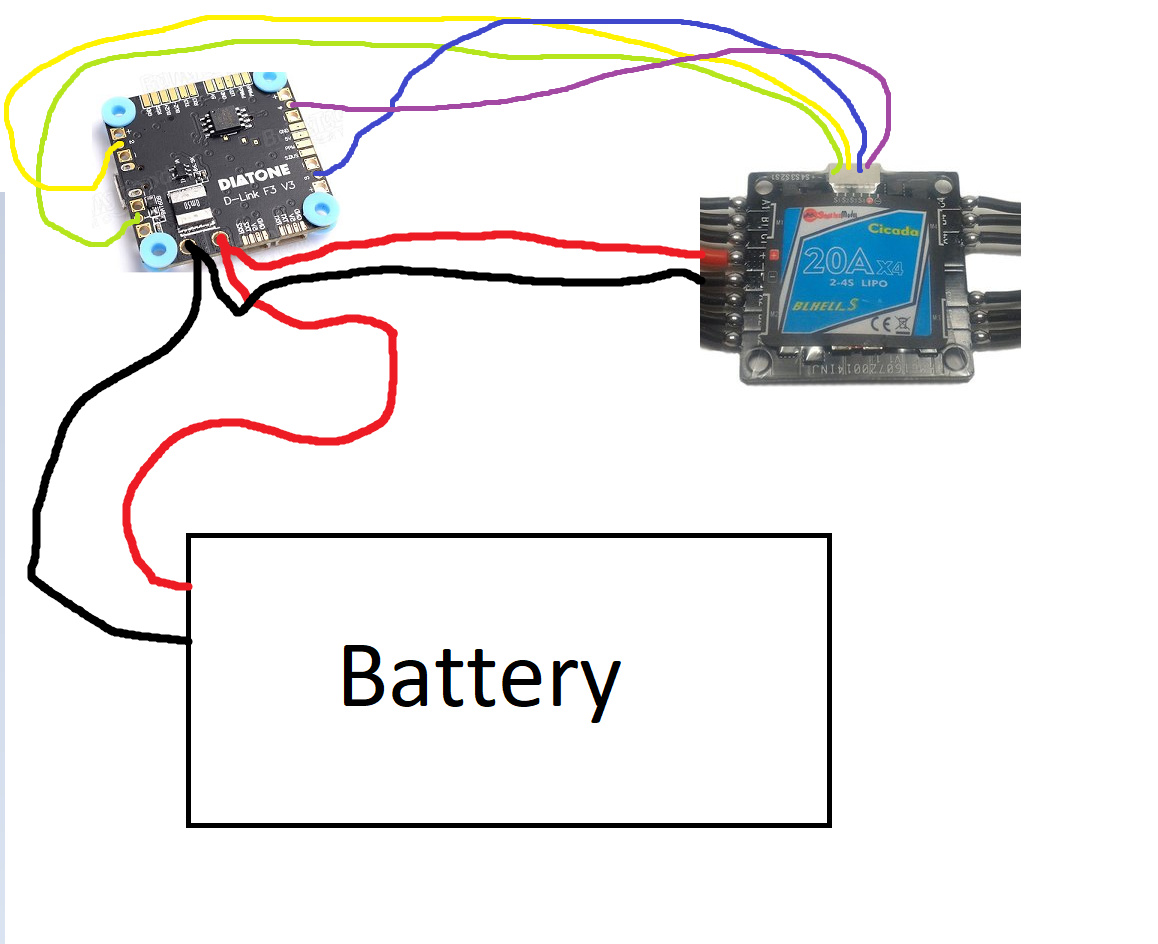
Wiring Cicada 4 in 1 ESC to Diatone FC with integrated PDB ...
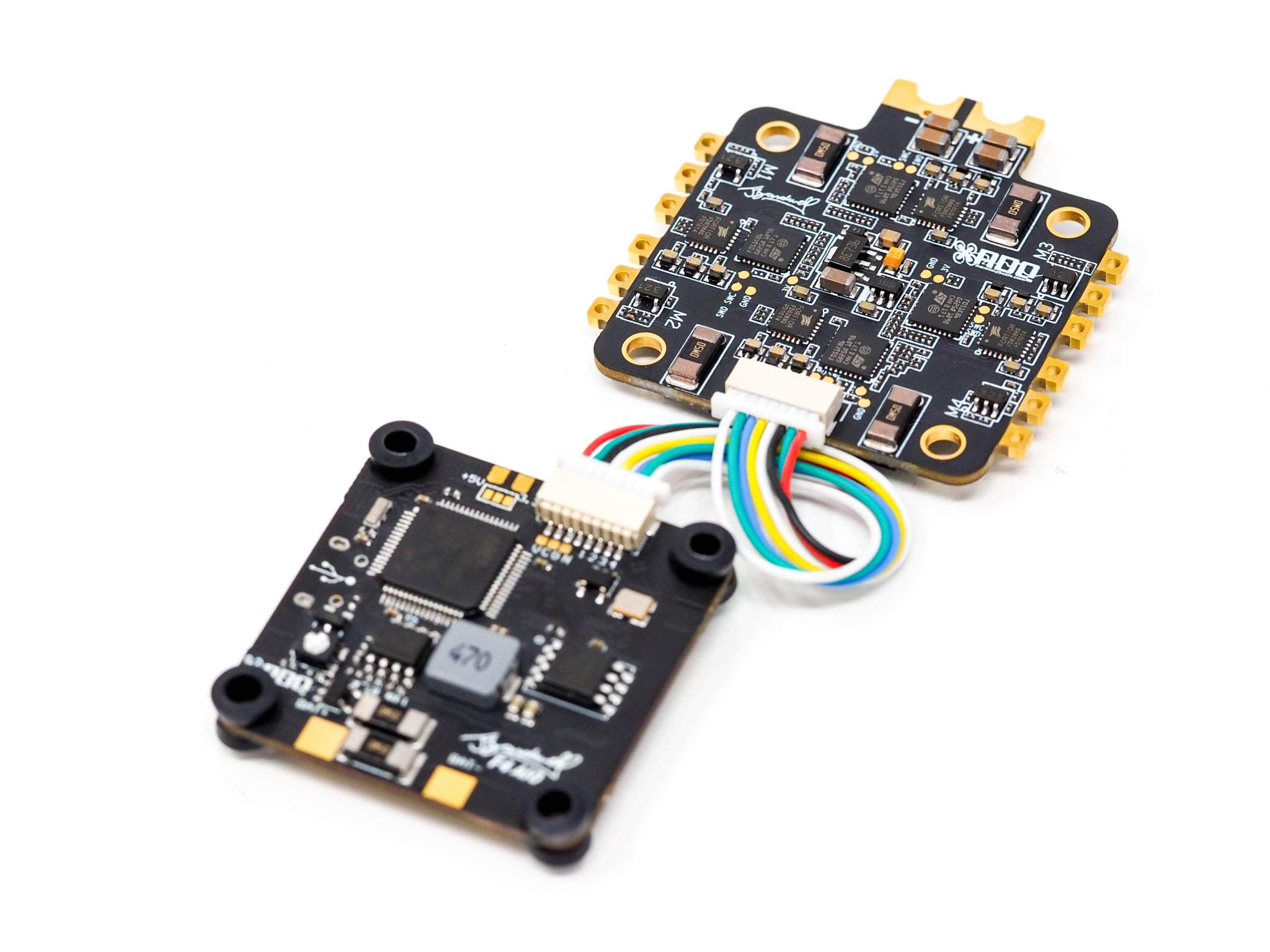
RADIX 2 4-in-1 ESC Connection - brainfpv Flight Controller - 4-in-1 ESC Connections. Every 4-in-1 ESC currently available has the following connections: Motor Signals (S1 .. S4 or M1 .. M4): These connections are used to send RPM commands (how fast the motor should turn) from the flight controller to each ESC. With bi-directional DSHOT, the same wire is also used by the ESC to send RPM information back to the flight controller.
Bardwell 32Bit 4-in-1 30A 6S ESC BLHeli_32 — AirBlade UAV
4 In 1 Esc Wiring Diagram - easywiring 4 in 1 esc wiring diagram. A 4in1 esc is more convenient to use as there is less messy wiring as the powering of each esc is done internally on the board. Connect the esc for motor 1 to the pdb pins marked m1 motor 6 s esc to the pins marked m6 etc. If have any questions about drone wiring diagram please contact.

Oscar Liang - Honestly, we should stop this mess and ...
Xrotor 20x20 stack 4in1 ESC for FPV pilots - HOBBYWING ... Meet XROTOR "FPV" Series - 20x20 4 in 1 stack ESC Model 20x20 Stack 40A 20x20 stack Nano (20A) SKU 30902045 30901068 BLHeli_32 DShot1200 BLHeli-S DShot600 Application 130-300mm FPVsDiagonal Wheelbase 130-280mm FPVsDiagonal Wheelbase Firmware HobbywingXRotor_BLHeli32 BLHeli-S A-H-50 16.5 LiPo Power input 3-6S Lipo 2-4S

DYS 4in1 F20A ESC Overview - Oscar Liang
SucceX-E 45A 2-6S BLHeli_S Dshot600 4-in-1 ESC ESC // SucceX-E 45A 2-6S BLHeli_S 4-in-1 ESC. - Dimension: 40*43mm. - Mounting Holes: 30.5*30.5mm/Φ3mm. - Weight: 14.4g. - Supports 2-6S Lipo input. - EFM8BB21 MCU, 24Mhz Runs BLHELI 16.X Firmware. - Current sensor: YES.

ESC wiring and connections - KISS documentation
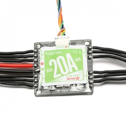
Racerstar RS20Ax4 20A 4 in 1 Blheli_S Opto ESC 2-4S Support ...

MAMBA F40 MK2 4IN1 40A ESC DSHOT600 4-6S ELECTRONIC SPEED CONTROLLER
Vector Flight Controller Wiring Diagram Wiring Diagram ...
XRotor Micro 4-in-1 60A ESC 6S BLHeli_32

65 Wiring Diagrams ideas | diy drone, diagram, drone design
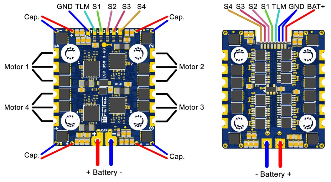
FETtec 4in1 ESC 35A Dshot2400 - Drone-FPV-Racer.com
![Flite Test FullSpeedRC Flight Controller & 4-in-1 ESC Stack [FLT-3055]](https://images.amain.com/images/large/flt/flt-3055.jpg)
Flite Test FullSpeedRC Flight Controller & 4-in-1 ESC Stack [FLT-3055]
drone full camera wiring diagram for Android - APK Download

XRotor Micro 60A 4in1 ESC BLHeli32 Dshot1200 6S for FPV ...
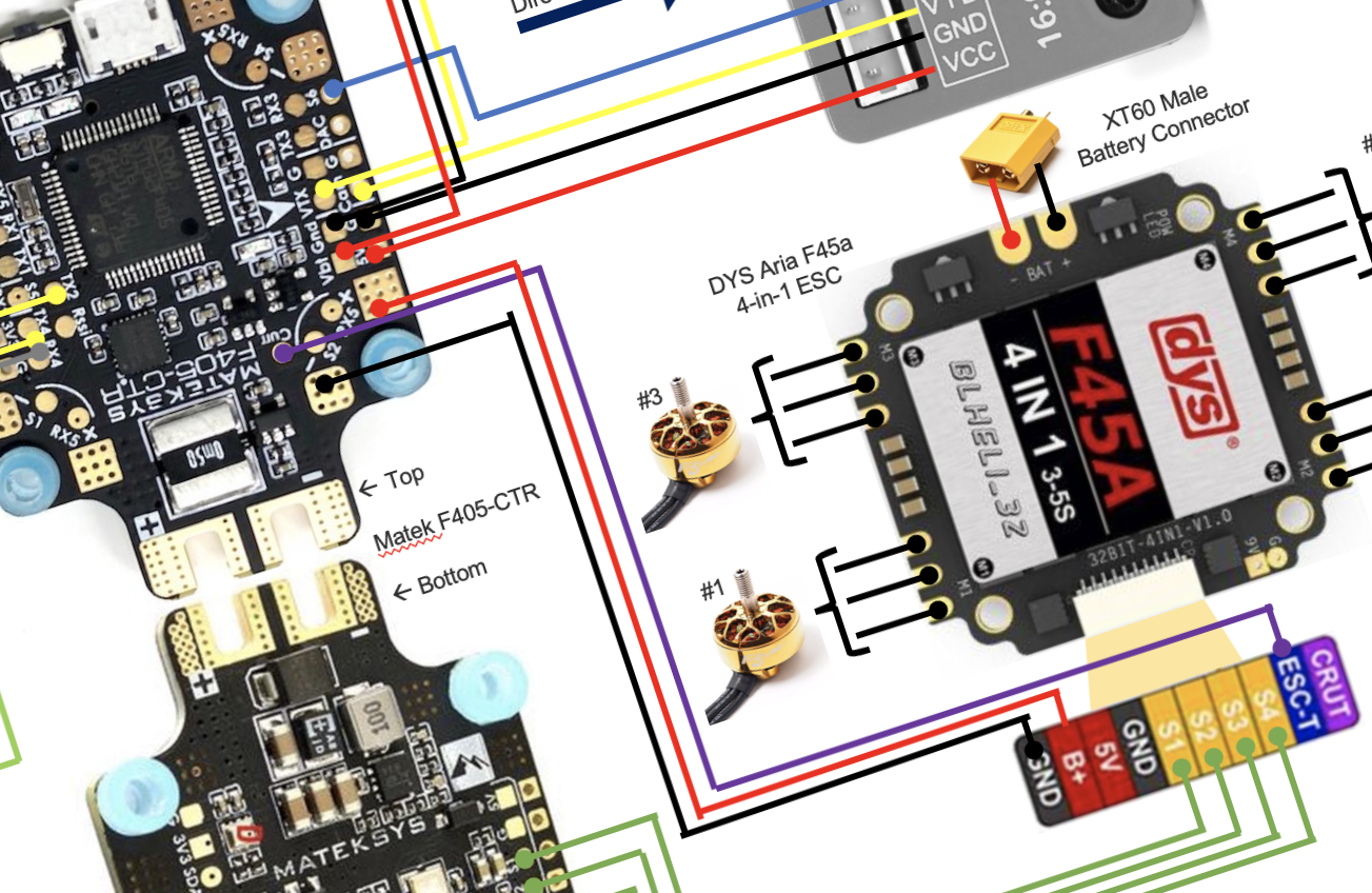
Wiring a Matek F405 to DYS Aria D45A 4 in 1 ESC – flyingsquirrel

Racerstar STAR20 20A detachable 4in1 ESC

HAKRC 35A 2-6S BLHeli_S 20x20 4-in-1 ESC
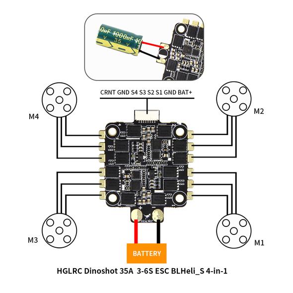
HGLRC DinoShot 35A 4-in-1 ESC

AKK 30A 4 IN 1 2-6S Brushless ESC BLHeli_S Electronic Speed Controller DShot150/300/600 Capable for Micro Racing Drones
Amazon.com: Spedix GS25 25A 4-in-1 2-4s BLHeli_32 Dshot ESC ...

Noxe F4 Repülés Vezérlő Tábla Integrált Osd / Nélkül ...

All-in-one FC/PDB and 4-in-1 ESC wiring -- series or parallel ...

Mini 25A 4-in-1 ESC BLHeli_S 20x20mm 2-4S ESC Dshot600 Oneshot Multishot- F3 20A | eBay

JHEMCU GHF411AIO Pro 35A F4 OSD Flight Controller Built in ...
Wiring Cicada 4 in 1 ESC to Diatone FC with integrated PDB ...

T-Motor Pacer P60 4-in-1 ESC - ProgressiveRC
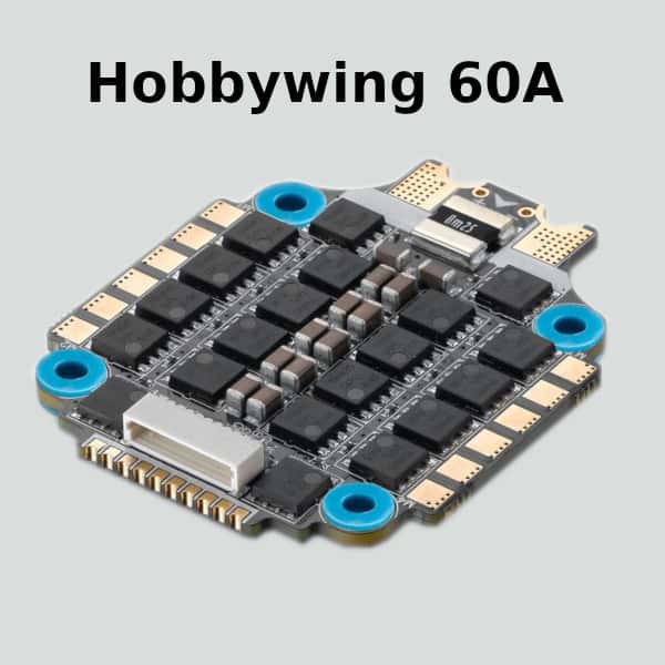
Wiring up the Hobbywing to Matek F722-SE
4 in 1 ESC Wiring & Set Up

DYS 4in1 F20A ESC Overview - Oscar Liang
0 Response to "44 4 in 1 esc wiring diagram"
Post a Comment