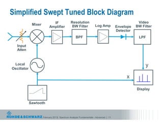
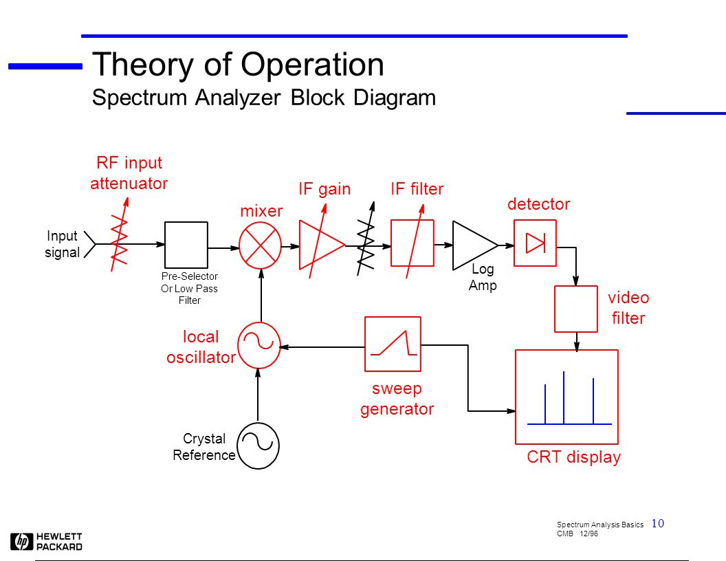
pectrum analyzer block diagram
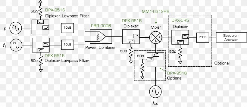
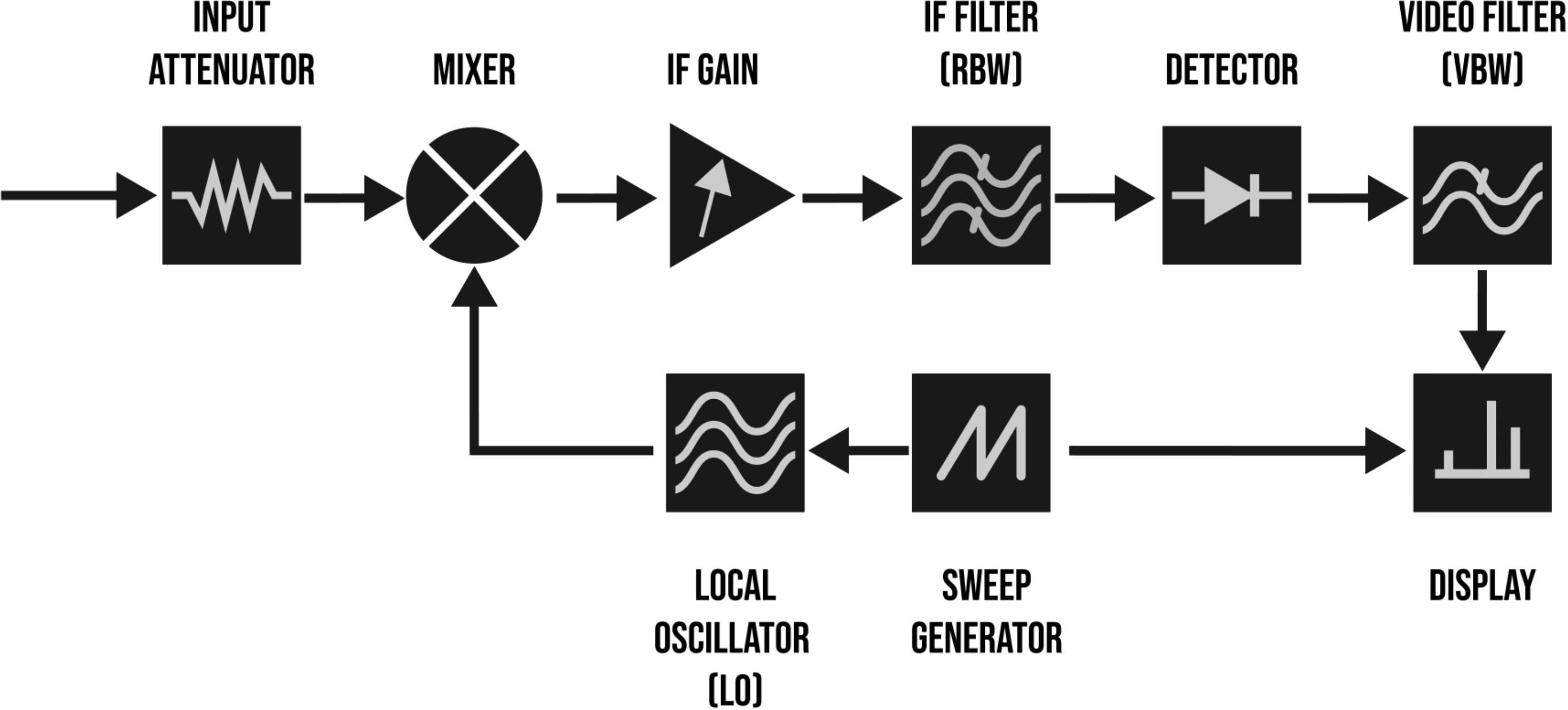
The figure below shows the block diagram representation of a spectrum analyzer with digital display: As we can see the spectrum analyzer is composed of components like RF attenuator, mixer, IF filter, detector, sweep generator, local oscillator and display unit. So, let us now understand the operation performed by each block individually. Block diagram for spectrum analyzer. Source publication A Technique to Accurately Predict EMI Noise Spectrum in Wide Frequency Ranges Based on the Principles of Spectrum Analyzers
Feb 04, 2019 · The block diagram of Parallel Filter Bank type of spectrum analyzer is shown in Figure. From the block diagram it can be seen that there are 32 narrow band filters. The input signal is connected in parallel to all the filters. The output of all the filters reaches the high speed scanner. The output from the scanner is supplied to a detector ...

Spectrum analyzer block diagram
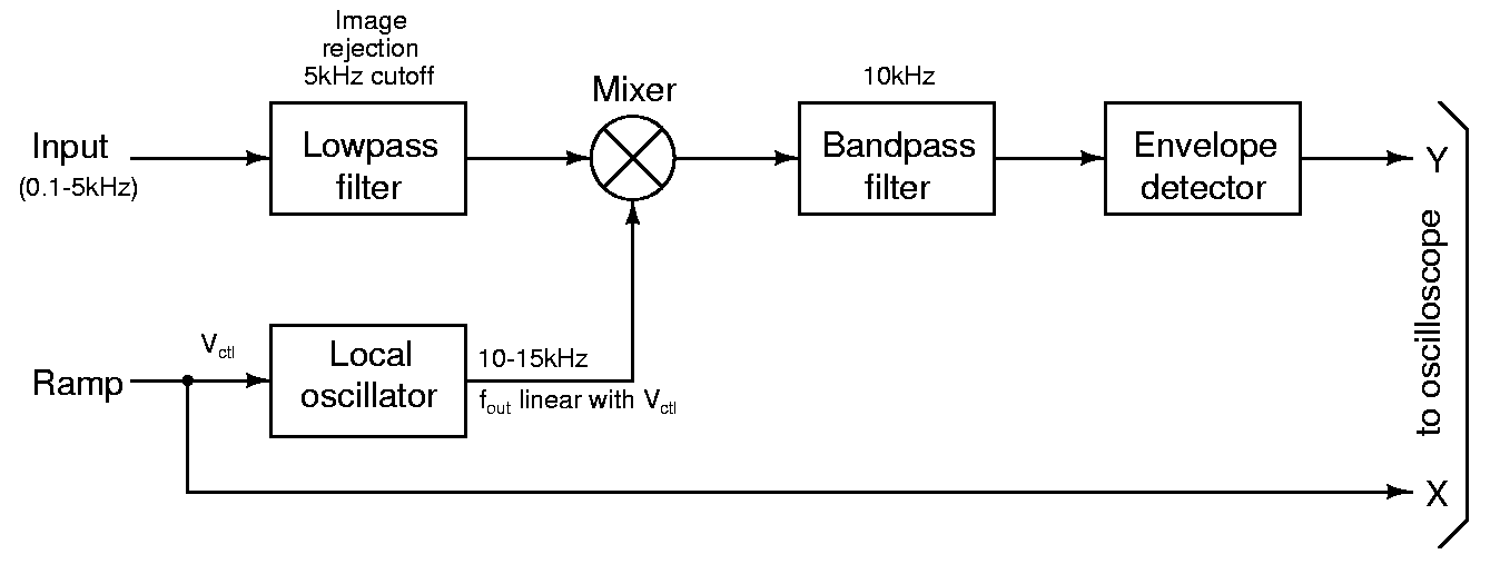
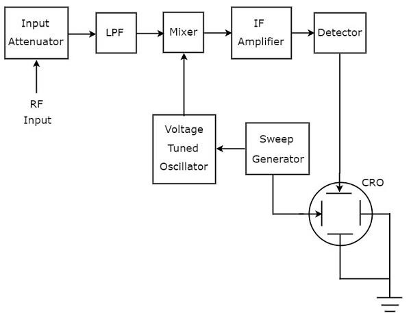
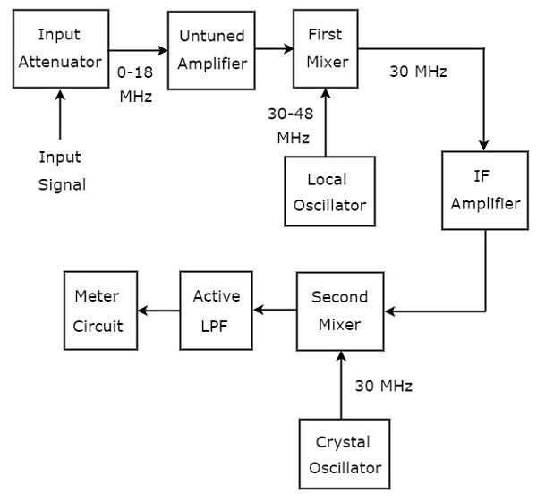
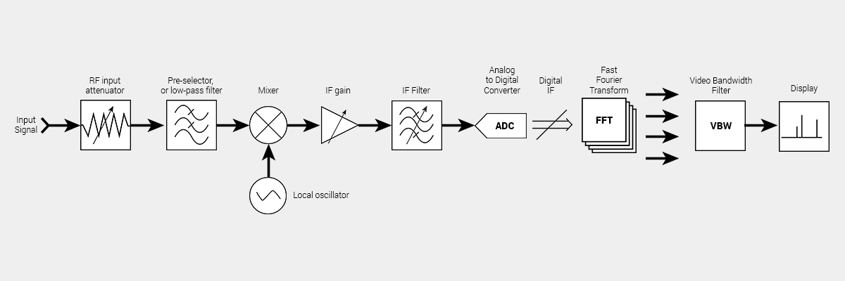
The spectrum analyzer, used for analyzing the signals are of RF range is called superheterodyne spectrum analyzer. Its block diagram is shown in below figure. The working of superheterodyne spectrum analyzer is mentioned below. The RF signal, which is to be analyzed is applied to input attenuator. If the signal amplitude is too large, then it ...
Spectrum analyzer block diagram. The spectrum analyzer, used for analyzing the signals are of RF range is called superheterodyne spectrum analyzer. Its block diagram is shown in below figure. The working of superheterodyne spectrum analyzer is mentioned below. The RF signal, which is to be analyzed is applied to input attenuator. If the signal amplitude is too large, then it ...
EA4EOZ, an amateur radio electronic enthusiast: Repairing an ...
Frequency Mixer Spectrum Analyzer Third-order Intercept Point ...
Block Diagram Of The Spectrum Analyzer - Audio Spectrum ...
courses:ec330_2009:spectrumanalyzer [Integrated Circuits and ...

Spectrum Analyzer Block Diagram | Parallel Filter Bank ...

Why Spectrum Analysis is Important - ppt download
.jpg)
Why and How to Use Spectrum Analyzers - Mega Depot

Spectrum Analyzer - Techplayon

Audio Spectrum Analyzer

Spectrum Analyzer Block Diagram | Parallel Filter Bank ...

Simplified spectrum analyzer block diagram. | Download ...
What is Spectrum Analyzer? Block Diagram, Working and ...

Spectrum analyzer working principle, used and applications

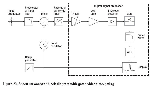
Spectrum Analysis Basics: Part 5 - Time Gating | Keysight Blogs

Block diagram for spectrum analyzer. | Download Scientific ...
Spectrum Analyzers

Spectrum Analysis Back to Basics Agilent Technologies Back
Spectrum Analyzer - Electronics Club Spectrum Analyzer
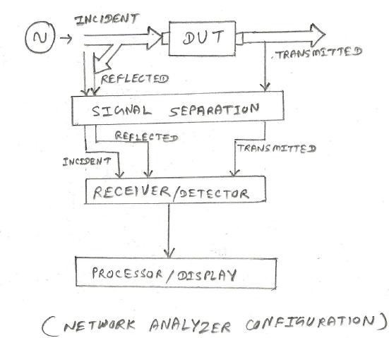
difference between spectrum analyzer vs network analyzer | basics

Spectrum Analysis Back to Basics Agilent Technologies Back

Signal Analyzer Fundamentals and New Applications

Agilent Technologies - 8 Hints for Spectrum Analysis
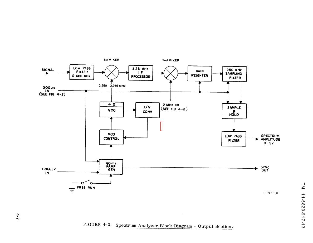
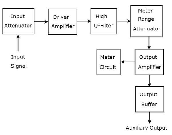
Figure 4-3. Spectrum Analyzer Block Diagram - Output Section

Spectrum Analyzer Block Diagram | Parallel Filter Bank ...

Real time spectrum analyzers vs. swept spectrum analyzers
A Study on BASICS OF A SPECTRUM ANALYZER
spectrum analyzer block diagram - Bald Engineer

Spectrum Analyzer Block Diagram | Parallel Filter Bank ...

Total harmonic distortion analyzer - Wikipedia

Review: Signal Hound BB60C real time 6 GHz spectrum analyzer ...
Spectrum Analyzer Fundamentals/Advanced Spectrum Analysis

Spectrum Analyzer Block Diagram | Parallel Filter Bank ...

Block Diagram Of The Spectrum Analyzer - Audio Spectrum ...
Wave Analyzers

EETimes - Signal Integrity Engineer's Companion: The Wireless ...

Vector signal analyzer - Wikipedia
SPECTRUM ANALYZER 9 kHz GHz - ppt download

Rohde & Schwarz: Spectrum Analyzer Fundamentals - RF Cafe
Wave Analyzers
Spectrum Analyzer 0...1750MHz
Agilent Technologies - 8 Hints for Spectrum Analysis

FFT Spectrum Analyzer: Fast Fourier Transform » Electronics Notes
Simplified Spectrum Analyzer Block Diagram | Signal Hound
SPECTRUM ANALYZER

Optical Spectrum Analyzer - an overview | ScienceDirect Topics
0 Response to "pectrum analyzer block diagram"
Post a Comment