43 fe fe3c phase diagram
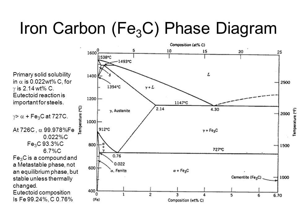
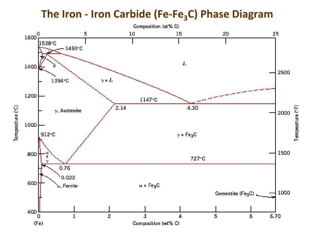
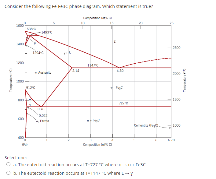
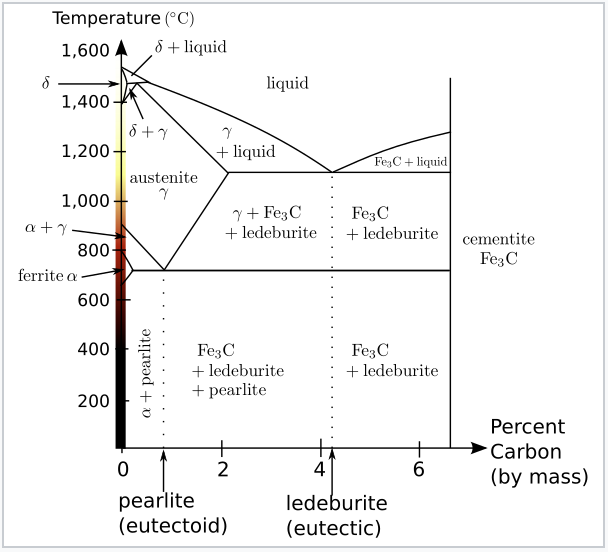
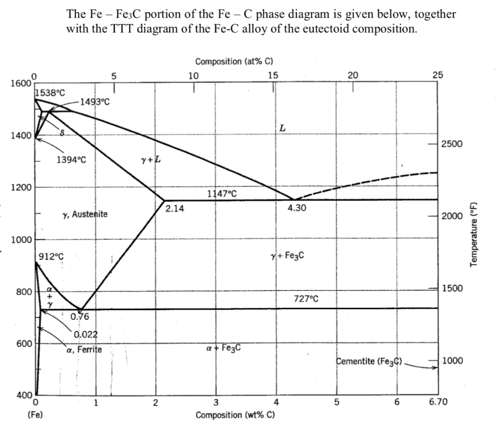
The Iron Carbide (Fe Fe3C) Phase Diagram - UPRM Pages 1-50 ... The Iron ‐ Iron Carbide (Fe‐Fe3C) Phase Diagram Reactions Phases Present Peritectic L + δ = γ Lat T=1493oC and 0.18wt%C δ ferrite delta Eutectic L = γ + Fe3C Bcc structure at T=1147oC and 4.3wt%C Paramagnetic Eutectoid γ = α + Fe3C γ austeniteat T=727oC and 0.77wt%C Fcc structure Non‐magnetic ductileMax. solubility of C α ferrite Fe3C cementitein ferrite=0.022% Bcc structure ... PDF The C-Fe (Carbon-Iron) System - gotrawama.eu In the present evaluation, the assessed stable Fe-C (graphite) and metastable Fe-Fe3C (cementite) equilibrium phase diagrams for 0 to 25 at.% C are based on thermodynamic calculations reported by [79Schl] and [84Oht].
eng.utq.edu.iq › sites › 4/2019/09The Iron Carbide (Fe Fe3C) Phase Diagram Phases in Fe–Fe 3 C Phase Diagram ¾α‐ferrite‐solid solution of C in BCC Fe •Stable form of iron at room temperature. • Transforms to FCC g‐austenite at 912 °C ¾γ‐austenite‐solid solution of C in FCC Fe • Transforms to BCC δ‐ferrite at 1395 °C

Fe fe3c phase diagram
Muddiest Point- Phase Diagrams V: Fe-Fe3C Microstructures ... This video answers the most frequently asked questions students have about iron- iron carbide phase diagram microstructures. If you have any questions or com... Draw Fe Fe3C diagram and explain Euctetoid, Eutectic and ... Draw Fe Fe3C diagram and explain Euctetoid, Eutectic and Peritectic transformations in Fe Fe3C. written 5.6 years ago by teamques10 ♣ 15k: ... Liquid-100 wt% →51.97wt% γ +Fe3C (48.11wt%) The phase mixture of austenite and cementite formed at eutectic temperature is called ledeburite. › metallurgy › ironIron-Carbon Equilibrium Diagram | Metallurgy Cementite, chemical formula Fe3C has a fixed carbon content of 6.67%, i.e., when iron has 6.67% carbon, then 100% cementite is obtained. Thus, this diagram (see bottom most horizontal line in (Fig. 1.22) which has components iron and cementite (100% Fe on one end to 100% cementite on the other end of the diagram) can rightly be called as iron-cementite diagram.
Fe fe3c phase diagram. Why isn't iron - iron carbide diagram considered as a ... Fe-Fe3C is not considered an equilibrium phase diagram, because Fe3C is behaving metastable in iron. It is not really a metallurgical reason but a thermochemical reason, in an equilibrium phase ... Phase Diagram of Steel - Metallurgy for Dummies The diagram shows iron and carbons combined to form Fe-Fe3C at the 6.67%C end of the diagram. The left side of the diagram is pure iron combined with carbon, resulting in steel alloys. Three significant regions can be made relative to the steel portion of the diagram. They are the eutectoid E, the hypoeutectoid A, and the hypereutectoid B. Iron-Iron carbide (Fe-Fe3C) Phase Equilibrium Diagram In this ... The diagram shows the phases present at various temperatures for very slowly cooled. Fe-C alloys with carbon content up to 6.67%. Information given by the ...4 pages Iron Carbide (Fe3c) - an overview | ScienceDirect Topics Iron carbide (Fe 3 C) is often labeled as the uncorroded portion of the steel. It is primarily associated with mild steels having a high carbon content and a ferritic-pearlitic microstructure. During corrosion of such steel, the ferrite phase dissolves and a porous iron carbide network is exposed (see Fig. 7.6).Given that iron carbide is an electronic conductor, this porous network serves as ...
Use this Fe-C phase diagram if required: Composition ... Transcribed image text: Use this Fe-C phase diagram if required: Composition (at% C) 10 15 20 25 16000 1538°C 1493°C 1400 8 L 2500 1394°C 7+Z 1200 1147°C 2.14 4.30 y Austenite 2000 Temperature (°C) 1000 Temperature (°F) 912°C y + Fezc 8001-a 1500 727°C 0.76 0.022 a, Ferrite 600 + Feyc Cementite (Fe3C) 1000 400 0 (Fe) 6 6.70 Composition (wt% C) 1. The Iron-Carbon Phase Diagram - IspatGuru Hence, the normal equilibrium diagram which is generally used is the metastable Fe-Fe3C diagram because it is relevant to the behaviour of most steels in practice. The details of the stable and metastable phase diagrams of the Fe-C system, especially on the Fe-rich side, are known much better than any other binary systems with similar complexity. Iron-Iron Carbide Phase Diagram | Material Engineering The Iron-Iron carbide (Fe-Fe 3 C) is defined by five individual phases and four invariant reactions. Five phases are- α-ferrite (BCC) Fe-C solid solution, γ-austenite (FCC) Fe-C solid solution, δ -ferrite (BCC) Fe-C solid solution, Fe 3 C (iron carbide) or cementite - an inter- metallic compound and liquid Fe-C solution. Iron Carbide (Fe-Fe C) Phase Diagram - Academic Uprm C Phase Diagram. ➢ α-ferrite - solid solution of C in BCC Fe. • Stable form of iron at room temperature. • Transforms to FCC g-austenite at 912 °C.67 pages
Fe-Fe3C Phase Diagram with approximate carbon levels of ... Download scientific diagram | Fe-Fe3C Phase Diagram with approximate carbon levels of HSLA (green), DP (pink) and TRIP (blue) [9]. from publication: Resistance Spot Welding of Advanced High ... Fe Fe3c Phase Diagram The Fe-Fe 3 C phase diagram for magnetic fields up to 18 T is presented in Fig. 9. The solid lines and curves in this figure are visual guides only. The broken line represents the A Cm line derived from reported data. The transition temperatures obtained in zero fields were in good agreement with the Fe-Fe 3 C phase diagram reported by Okamoto. Fe-Fe3C binary phase diagram in high magnetic fields ... The Fe-Fe 3 C binary phase diagram under high magnetic fields up to 21 T was investigated by a differential thermal analysis. Applying a magnetic field of 18 T, the α-γ transformation temperature T α-γ for pure iron increased quadratically from 1181 K (a zero field) to 1206 K. With increasing magnetic field strength, the transformation temperature A c1 (α-Fe + cementite → α-Fe + γ ... What is Fe-Fe3C phase diagram? - Swirlzcupcakes.com What is Fe-Fe3C phase diagram? The Fe-C phase diagram is a fairly complex one, but we will only consider the steel part of the diagram, up to around 7% carbon. α-ferrite - solid solution of C in BCC Fe • Stable form of iron at room temperature. The maximum solubility of C is 0.022 wt%. Transforms to FCC γ-austenite at 912 °C.
(PDF) Fe-C Phase Diagram | Bogdan Chiriac - Academia.edu • On the right the phase diagram only extends to 6.70 wt%C • At this concentration the intermediate compound iron carbide, or cementite (Fe3C) is formed • This is sufficient to describe all of the Fe3C steels and cast irons Pure Fe cementite used today.
Iron–Iron Carbide (Fe–Fe3C) Phase Diagram - nifft The Fe-C phase diagram is a fairly complex one, but we will only consider the steel part of the diagram, up to around 7% carbon. Page 2. Phases in Fe–Fe3C Phase ...7 pages
fractory.com › iron-carbon-phase-diagramIron-Carbon Phase Diagram Explained [with Graphs] - Fractory The boundaries, intersecting each other, mark certain regions on the Fe3C diagram. Within each region, a different phase or two phases may exist together. At the boundary, the phase change occurs. These regions are the phase fields. They indicate the phases present for a certain composition and temperature of the alloy.
› time-temperatureTTT Diagram - Metallurgy for Dummies Phase Diagram of Steel The diagram shows iron and carbons combined to form Fe-Fe3C at the 6.67%C end of the diagram. The left side of the diagr... Inclusions Phenomena at Steelmaking One tonne of steel, a cube with sides of about 0,5m, contains between 1012 and 1015 inclusions which can occupy up to ab... Futuristic Materials part 2
PDF The iron-iron carbide (Fe-Fe3C) phase diagram The iron-iron carbide (Fe-Fe3C) phase diagram 1 The iron-iron carbide (Fe-Fe3C) phase diagram Microstructures of iron α- ferrite austenite 2 Interstitial sites of FCC Interstitial sites of BCC 3 Microstructure in iron-carbon alloys REutectic-- pearlite Hypoeutectoid alloys 4 Hypereutectoid alloys
Muddiest Point- Phase Diagrams III: Fe-Fe3C Phase Diagram ... This is part three in a series of screencasts about phase diagrams. This video introduces major features of the Fe-Fe3C phase diagram, steel classification, ...
Fe-Fe3C T-T-T Diagram - Metallurgy for Dummies Fe-Fe 3 C T-T-T Diagram, Adapted from Callister pg. 295, Fig. 10.6 The time-temperature transformation curves correspond to the start and finish of transformations which extend into the range of temperatures where austenite transforms to pearlite. Above 550 C, austenite transforms completely to pearlite.
staff.emu.edu.tr › emirtascioglu › DocumentsFe-C Diagram - Eastern Mediterranean University L+Fe 3 C d (Fe) C, wt%C 1148ºC T(ºC) a Adapted from Figs. 9.24 and 9.32,Callister & Rethwisch 8e. (Fig. 9.24 adapted from Binary Alloy Phase Diagrams, 2nd ed., Vol. 1, T.B. Massalski (Ed.-in-Chief), ASM International, Materials Park, OH, 1990.) (Fe-C System) 6 C 0 Fe 3 C g g g g g g g g g g g Adapted from Fig. 9.33, Callister & Rethwisch 8e ...
Fe Fe3c Phase Diagram - schematron.org Fe - Fe3C Phase Diagram 5. Fig 1 Iron Carbon phase diagram. The diagram shown in Fig 1 actually shows two diagrams i) the stable iron-graphite diagram (dashed lines) and the metastable Fe-Fe3C diagram. The stable condition usually takes a very long time to develop specially in the low temperature and low carbon range hence the metastable ...
What is Cementite - Fe3C - Definition | Material Properties In the figure, there is the iron-iron carbide (Fe-Fe3C) phase diagram. The percentage of carbon present and the temperature define the phase of the iron carbon alloy and therefore its physical characteristics and mechanical properties. The percentage of carbon determines the type of the ferrous alloy: iron, steel or cast iron.
Calculation Of The Fe-fe3c Phase Equilibrium Diagram - ID ... Calculation Of The Fe-fe3c Phase Equilibrium Diagram In heat treatment processes of steel the very important role plays the Fe-Fe3C phase equilibrium diagram. It enables the selection of the temperature of austenitisation in respect to carbon content in steel as well as to predict the microstructure composition of annealed steel.
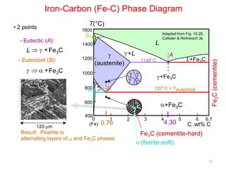
The iron-iron carbide (Fe-Fe3C) phase diagram Review Fe-C phase diagram • 2 important points-Eutectoid (B): γ⇒α+Fe 3C-Eutectic (A): L ⇒γ+Fe 3C Fe 3 C (cementite) 1600 1400 1200 1000 800 600 400 0 12 3 4 5 66.7 L γ (austenite) γ+L γ+Fe 3C α+Fe 3C α + γ L+Fe 3C δ (Fe) C o, wt% C 1148°C T(°C) α 727°C = Teutectoid A R S 4.30 Result: Pearlite = alternating layers of αand Fe ...
PDF APPLICATIONS OF Fe-C PHASE DIAGRAM PHASE TRANSFORMATION Liquid to Austenite •Eutectic transformation-1148C, •C-2.11%-4.3% •Eutectic transformation-4.3% C, 1148C •Eutectic transformation L-γ+F
› RakeshSingh125 › fe-cdiagramFe-C diagram - SlideShare Nov 18, 2013 · Iron–Carbon Phase Diagram • In their simplest form, steels are alloys of Iron (Fe) and Carbon (C). • The Fe-C phase diagram is a fairly complex one, but we will only consider the steel and cast iron part of the diagram, up to 6.67% Carbon. 3. Fe – C Equilibrium Diagram 4.
› metallurgy › ironIron-Carbon Equilibrium Diagram | Metallurgy Cementite, chemical formula Fe3C has a fixed carbon content of 6.67%, i.e., when iron has 6.67% carbon, then 100% cementite is obtained. Thus, this diagram (see bottom most horizontal line in (Fig. 1.22) which has components iron and cementite (100% Fe on one end to 100% cementite on the other end of the diagram) can rightly be called as iron-cementite diagram.
Draw Fe Fe3C diagram and explain Euctetoid, Eutectic and ... Draw Fe Fe3C diagram and explain Euctetoid, Eutectic and Peritectic transformations in Fe Fe3C. written 5.6 years ago by teamques10 ♣ 15k: ... Liquid-100 wt% →51.97wt% γ +Fe3C (48.11wt%) The phase mixture of austenite and cementite formed at eutectic temperature is called ledeburite.
Muddiest Point- Phase Diagrams V: Fe-Fe3C Microstructures ... This video answers the most frequently asked questions students have about iron- iron carbide phase diagram microstructures. If you have any questions or com...





![06-Iron (Fe) - Iron Carbide(Fe3C) Phase Diagram - [PDF Document]](https://reader020.staticloud.net/reader020/html5/20190929/552ccc254a79590e7d8b47f4/bg4.png)








0 Response to "43 fe fe3c phase diagram"
Post a Comment