44 carbon steel phase diagram
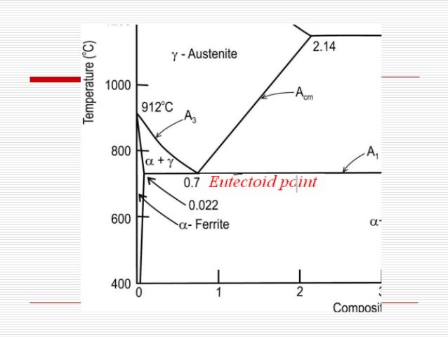
Iron Carbon Phase or Equilibrium Diagram or Iron Carbide ... Iron carbon phase diagram austenite This is also known as γFe. When we heat this solution, it converts into ferrite at a temperature above 2543°F. Austenite is usually unstable at temperatures below 727°C. This phase is non-magnetic in nature, and it changes rapidly. Fundamentals of Carbon Steel Part 1 - Phases ... The solubility of carbon in austenite is approximately 0.83 wt% (the location of the eutectoid in the iron-carbon phase diagram). Until the A3 temperature is reached, the structure will be a mixture of ferrite and austenite.
Medium-Carbon Steels - an overview | ScienceDirect Topics Straightening Carbon Steel Shafts Repair Techniques for Carbon Steel Shafts. For medium carbon steel shafts (0.30 to 0.50 carbon), three general methods of straightening the shaft are available. Shafts made of high alloy or stainless steel should not be straightened except on special instructions that can only be given for individual cases.

Carbon steel phase diagram
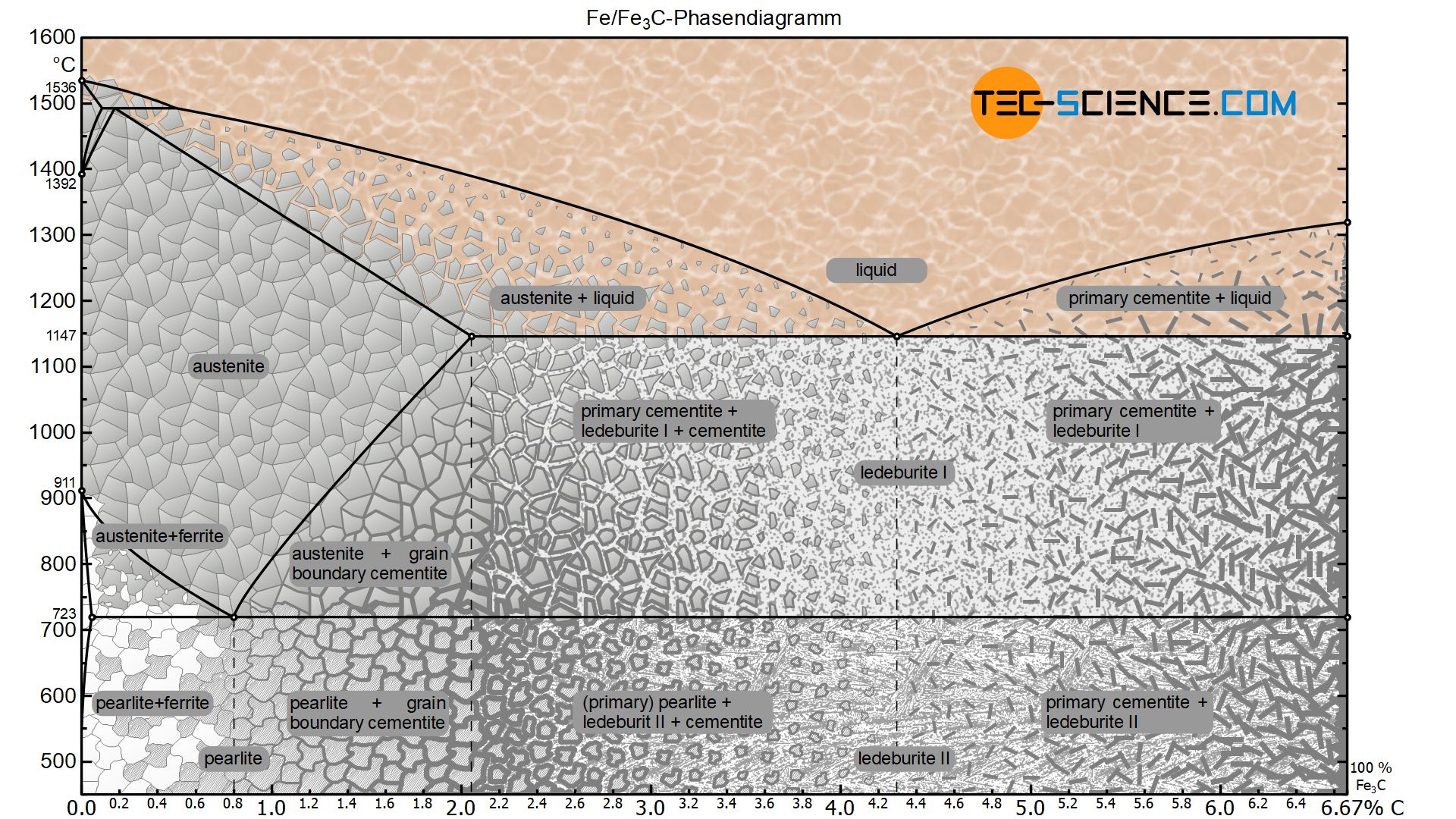
Welding of Austenitic Stainless Steel - TWI By varying the amounts of these elements, the steel can be made to be fully austenitic or can be designed to contain a small amount of ferrite; the importance of this will be discussed later. In 1949 Anton Schaeffler published a constitutional or phase diagram that illustrates the effects of composition on the microstructure. Metallography of Steels - University of Cambridge The phase diagram illustrates the domains in which particular phases or combinations of phases are stable, and contains information about their equilibrium compositions. Equilibrium phase fractions can also be estimated from a knowledge of the carbon concentration of the steel and an application of the lever rule. Iron-Carbon/Cementite Phase Diagram | Steel Metallurgy for ... This appendix includes two annotated iron-carbon (Fe-C) phase diagrams. One is a poster-size diagram showing iron-carbon phases up to 7 wt% C along with representative microstructures. The other diagram is close-up view showing the phases that occur from 0 to 1.2 wt% C.
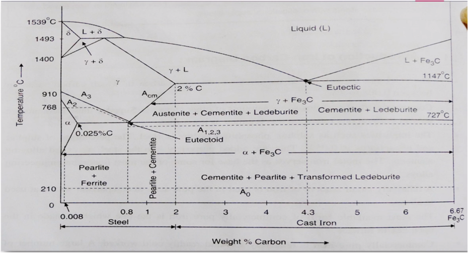
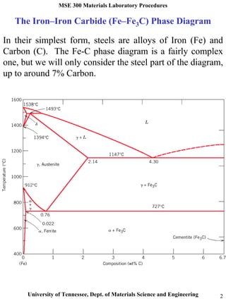
Carbon steel phase diagram. Phase diagram - Wikipedia A complex phase diagram of great technological importance is that of the iron–carbon system for less than 7% carbon (see steel). The x-axis of such a diagram represents the concentration variable of the mixture. The steel phase diagram - YouTube No phase diagram is more important to materials scientists than the Fe-C phase diagram because it allows us to explain many of the different types of steels.... PDF Lecture 19: Eutectoid Transformation in Steels: a typical ... Martensite is not shown in the equilibrium phase diagram of the iron-carbon system because it is a metastable phase, the kinetic product of rapid cooling of steel containing sufficient carbon. • Bainite: first described by E. S. Davenport and Edgar Bain, is a phase that exists in steel microstructures after certain heat treatments. The Iron-Iron Carbide Equilibrium Diagram Depending on carbon content, it is common practice to divide the iron-iron carbide diagram into two parts. Alloys containing less than 2 percent carbon are known as steels and alloys containing more than 2 percent carbon are known as cast irons. The steel range is further subdivided by the eutectoid carbon content (0.8 percent C).
Phase Diagram - Industrial Metallurgists The phase diagram indicates that an iron-carbon alloy with 0.5% carbon held at 900 °C will consist of austenite, and that the same alloy held at 650 °C will consist of ferrite and cementite. Furthermore, the diagram indicates that as an alloy with 0.78% carbon is slow cooled from 900 °C, it will transform to ferrite and cementite at about 727 °C. Iron-Carbon Phase Diagram Explained [with Graphs] - Fractory 10-03-2020 · Alloy steel elements such as nickel, manganese, chromium, and molybdenum affect the position of these boundaries on the phase diagram. The boundaries may shift in either direction depending on the element used. For example, in the iron carbon phase diagram, addition of nickel lowers the A3 boundary while the addition of chromium raises it. Iron-carbon (Steel) Phase Diagram w/ Pro-Eutectoid Step ... A Materials Science problem that calculates the proeutectoid ferrite,,eutectoid ferrite, and cementite weight fractions and masses of a 0.3% C steel as it co... PDF Phase Behavior in Iron/Carbon System 5 FCC Martensite (non equilibrium BCT phase from quench of γ) BCC Orthorhombic Iron/Carbon Phase Diagram Iron shows a eutectic with Carbon allowing for a lower melting alloy Body Centered Tetragonal 6 7 8 Carbon content can be reduced by reaction with oxygen and stirring 9 10 Eutectoid Steel Pearlite 11 Time-Temperature-Transformation Diagram 12
Making low-alloyed steel strong and tough by designing a ... The microstructure of the UFG F/M layered steel with 80% rolling reduction is shown in Fig. 2, where, the horizontal and vertical arrows represent normal and rolling directions (ND and RD), respectively.As shown in Fig. 2a and b, SEM and TEM analyses reveal that the present steel has a dual-phase layered microstructure comprising of UFG martensitic and ferrite lamellae. Alloy steel - Wikipedia The simplest steels are iron (Fe) alloyed with carbon (C) (about 0.1% to 1%, depending on type) and nothing else (excepting negligible traces via slight impurities); these are called carbon steels. However, the term "alloy steel" is the standard term referring to steels with other alloying elements added deliberately in addition to the carbon. Phase Diagram for Iron Carbon Alloys | Steel | Metallurgy ... The iron-carbon diagram tells which of the three steel phases are preset, at a given temperature and carbon concentration, when the alloy is cooled or heated slowly enough so that it remains in a state of equilibrium. 4. Pearlite: Metalloid - Wikipedia A metalloid is a type of chemical element which has a preponderance of properties in between, or that are a mixture of, those of metals and nonmetals.There is no standard definition of a metalloid and no complete agreement on which elements are metalloids. Despite the lack of specificity, the term remains in use in the literature of chemistry.
Iron –carbon phase diagram
Phase Diagrams - DT Online The Phase Diagram shows that for Steels with less than about 0.8% Carbon (i.e. Hypo Eutectic Steel) the mix solidifies into a two phase structure containing Ferrite which is very Soft and Ductile, and a layered structure of both Ferrite and Cementite (aka Iron Carbide) which is very Hard and Brittle - really a Ceramic.
Steels - An Introduction to Heat Treatment
40 phase diagram of steel - Wiring Diagrams Manual The diagram shows iron and carbons combined to form Fe-Fe3C at the 6.67%C end of the diagram. Carbon Steels and the Iron-Carbon Phase Diagram - IspatGuru 06-03-2016 · Because this temperature-composition point lies in the central region, the steel must be a mixture of ferrite and austenite, two examples of which are shown at the left side of ...
IRON CARBIDE EQUILIBRIUM DIAGRAM | Marine Inbox
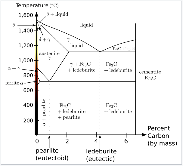
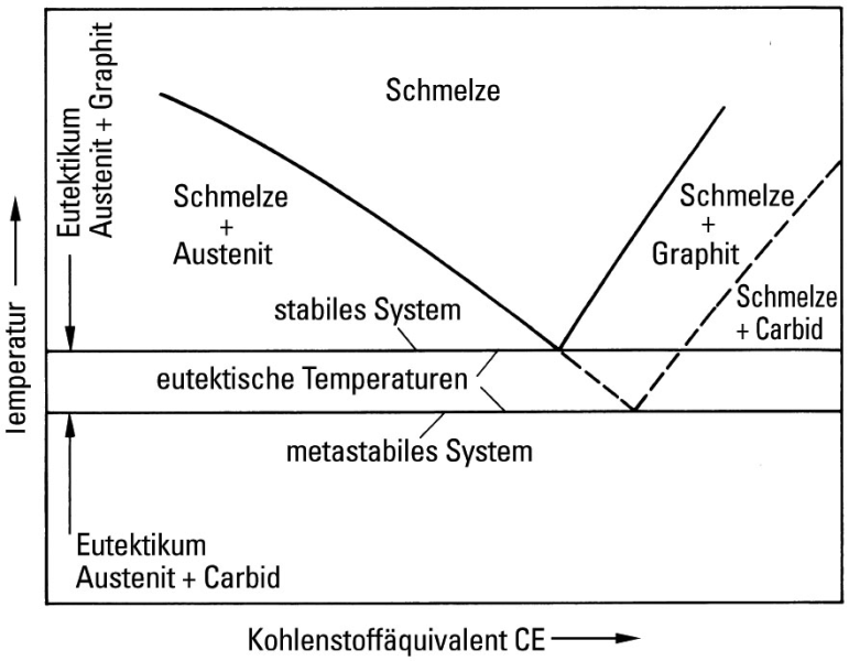
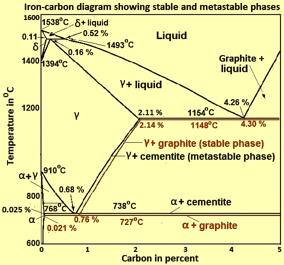
The Iron Carbon Phase Diagram For plain carbon steel with carbon concentrations below 2 %, you needn't worry, indeed. Graphite is never formed and the usual phase diagram covers everything nicely. For cast-iron, with carbon concentrations up to a few percent you need to worry. Graphite might form, depending on conditions.
Determination of microstructure and phase fractions in steels ...
Phase Diagram of Steel - Metallurgy for Dummies The diagram shows iron and carbons combined to form Fe-Fe3C at the 6.67%C end of the diagram. The left side of the diagram is pure iron combined with carbon, resulting in steel alloys. Three significant regions can be made relative to the steel portion of the diagram. They are the eutectoid E, the hypoeutectoid A, and the hypereutectoid B.
Solved The phase diagram of Iron – Carbon: Consider a 94 ...
What are Properties of Carbon Steel - Definition ... Low-carbon steel is a multi-element substance, principally of iron, with additions of carbon and impurities. The thermal conductivity of wrought iron is around 50 W/(m.K). The heat transfer characteristics of a solid material are measured by a property called the thermal conductivity , k (or λ), measured in W/m.K .
7.4: Iron and Steel - Chemistry LibreTexts
Effect of alloying elements in steel and Phase diagram Carbon Steel: Carbon steel is steel with carbon percentage up to 2% with no ternary alloying addition. Carbon steel is further divided into low carbon, medium and high carbon steel. Alloy Steel: If one or more ternary alloying elements along with carbon are present in steel, than it is termed as Alloy steel.
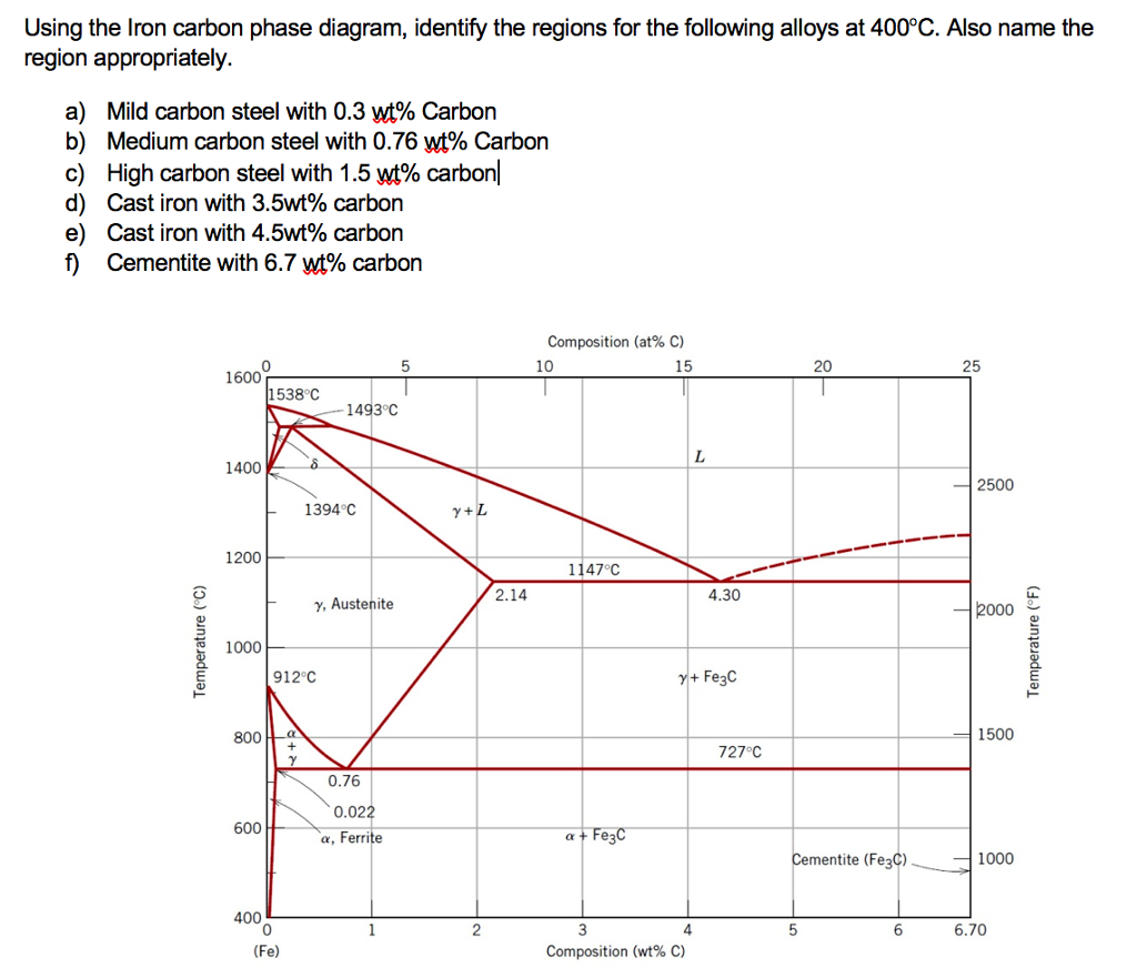
Solved Using the Iron carbon phase diagram, identify the ...
Iron Carbon Equilibrium Diagram with Explanation [Phase ... Nov 28, 2021 · The Iron carbon equilibrium diagram (also called the iron carbon phase diagram) is a graphic representation of the respective microstructure states of the alloy iron – carbon (Fe-C) depending on temperature and carbon content. The iron carbon phase diagram is commonly used to fully understand the various phases of steel and cast iron. Steel ...
Iron Phase Diagram - Roy Mech
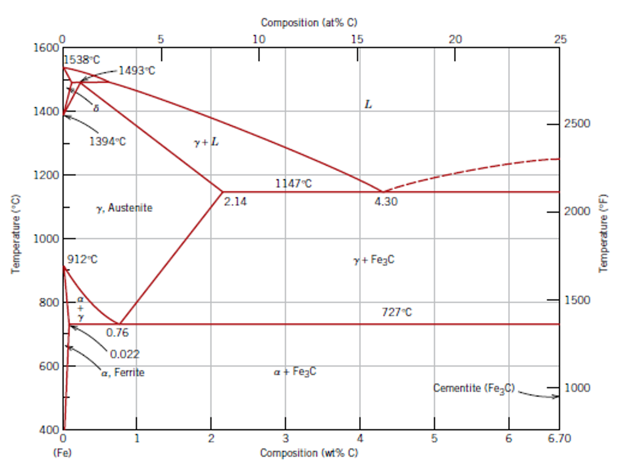
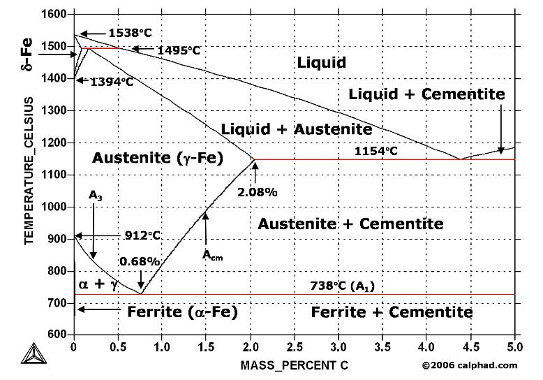
Carbon Steels and the Iron-Carbon Phase Diagram - IspatGuru The Fe-C phase diagram provides temperature-composition map of where the two phases (austenite and ferrite) occur. It also indicates where mixtures of these two phases can be expected. The Fe- C phase diagram is shown in Fig 2. In pure iron, austenite transforms to ferrite on cooling to 912 deg C.
Iron-carbon phase diagram
Phase Diagrams, TTT plots & CCT diagrams | beng-project Iron-Iron Carbide Phase Diagram - Callister Austenite is a polymorph of iron, in a face centred cubic (FCC) structure. Carbon is relatively soluble in this phase (up to 2% C at 1100°C). It is therefore found in mild carbon steel above the eutectoid temperature of 727°C.

Fe-Carbon Phase Diagram - ppt video online download
Use the iron carbon phase diagram shown in Figure 2 ... Transcribed image text: Use the iron carbon phase diagram shown in Figure 2 to answer the following questions for a 1.50 wt% C steel of mass 150 kg that is held at 750 °C. (0) What phases are present at 750 °C? What is the carbon content of each phase? (5 marks) The above steel sample is slow cooled to room temperature.
phase diagram iron carbon | Metallurgy for Dummies
TTT Diagram Basic - TTT diagram for steel, eutectoid steel Time-Temperature-Transformation (TTT) diagram or S-curve refers to only one steel of a particular composition at a time, which applies to all carbon steels.This diagram is also called as C-curve isothermal (decomposition of austenite) diagram and Bain’s curve.
materials -
PDF Chapter Outline: Phase Diagrams Component- chemically recognizable species (Fe and C in carbon steel, H2O and Sucrose in sugar solution in water). A binary alloy contains two components, a ternary alloy - three, etc. Phase- a portion of a system that has uniform physical andchemical characteristics.

What is Ferrite, Cementite, Pearlite , Martensite, Austenite
PDF IRON CARBON PHASE DIAGRAM - Higher Technological Institute A map of the temperature at which different phase changes occur on very slow heating and cooling in relation to Carbon, is called Iron- Carbon Diagram. Iron- Carbon diagram shows - the type of alloys formed under very slow cooling, proper heat-treatment temperature and

Iron-Carbon Equilibrium Phase Diagram ... | Diagram ...
Iron-Carbon/Cementite Phase Diagram | Steel Metallurgy for ... This appendix includes two annotated iron-carbon (Fe-C) phase diagrams. One is a poster-size diagram showing iron-carbon phases up to 7 wt% C along with representative microstructures. The other diagram is close-up view showing the phases that occur from 0 to 1.2 wt% C.

Image:Phase diag iron carbon-colour temp.png - Wikipedia, the ...
Metallography of Steels - University of Cambridge The phase diagram illustrates the domains in which particular phases or combinations of phases are stable, and contains information about their equilibrium compositions. Equilibrium phase fractions can also be estimated from a knowledge of the carbon concentration of the steel and an application of the lever rule.

File:Phase diagram of carbon steel jp.svg - Wikimedia Commons
Welding of Austenitic Stainless Steel - TWI By varying the amounts of these elements, the steel can be made to be fully austenitic or can be designed to contain a small amount of ferrite; the importance of this will be discussed later. In 1949 Anton Schaeffler published a constitutional or phase diagram that illustrates the effects of composition on the microstructure.

iron carbon phase diagram - Google Search | Metal working ...

Iron-Carbon Diagram, Transformation in steel, Transformation ...

Phase Diagrams - DT Online

Steel - Wikipedia
The Iron-Carbon Phase Diagram – IspatGuru

Structure of plain steel :: Total Materia Article
Carbon Steel.
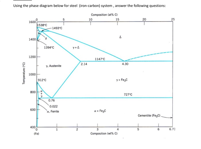
Solved Using the phase diagram below for steel (iron-carbon ...
Iron-Carbon Phase
The Iron - Iron Carbide (Fe-Fe C) Phase Diagram
Iron-Carbon Phase diagram [12] | Download Scientific Diagram

Delta Iron - an overview | ScienceDirect Topics
![Iron-Carbon Diagram Explanation [PDF]](https://mechanicalenotes.com/wp-content/uploads/2018/10/Iron-Carbon-Phase-diagram-feature-image.png)
Iron-Carbon Diagram Explanation [PDF]

Metastable austenitic stainless steels — Sandvik Materials ...
Material Science, The Iron Carbon Phase Diagram, Part 1
Iron Phase Diagram - Roy Mech

Sparky's Sword Science: Alloys, Microstructures and Phase ...

Iron-carbon phase diagram - Edelstahl härten
What is the difference between an iron carbon and a phase ...

Cast Iron; 9.5.1 General Remarks
![Iron-Carbon Phase Diagram Explained [with Graphs]](https://fractory.com/wp-content/uploads/2020/03/Phase-diagram-of-steel-and-cast-iron.jpg)
Iron-Carbon Phase Diagram Explained [with Graphs]
Iron Carbon Phase Diagram
Iron-Carbon Phase Diagram Its defined as:- A map of the ...

The Heat Treat Doctor IndustrialHeating January 22nd Edition

Please answer the following question regarding the iron-iron ...

The iron-carbon phase diagram | Download Scientific Diagram
Phase Diagrams:
When steel rusts, what is the fate of the carbon? - Quora
0 Response to "44 carbon steel phase diagram"
Post a Comment