44 uml vs er diagram
What is the Difference Between Class Diagram and Entity ... A class diagram is a UML type static structure diagram that describes the structure of a system by showing the system's classes, their attributes and relationships among objects while ERD is a visual representation of data based on the ER model that describes how entities are related to each other in the database. Entity relationship diagram example (UML notation ... This entity relationship diagram example template can help you: - Illustrate how entities relate to each other within a system using UML notation. - Design or debug relational databases. - Share ideas and collaborate with colleagues. Open this template to view a detailed example of an entity relationship diagram that you can customize to your use case.
JSONSchema To UML: Tool to Generate UML diagrams from JSON ... JSONSchema-to-UML has been developed as part of a collaborative project with Cmind. The tool analyzes JSON Schema definitions and generates a UML Class Diagram including the data elements as concepts, attributes, and relationships. By providing a graphical representation, developers can easily visualize the data model behind a set of JSON ...
Uml vs er diagram
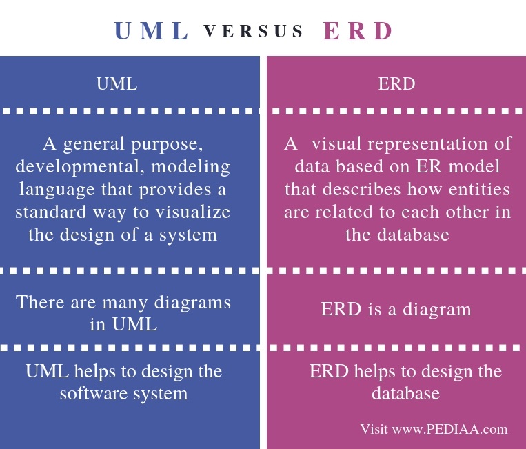
What is the Difference Between UML and ERD - Pediaa.Com The main difference between UML and ERD is that UML is a modeling language that represents a system or a software visually while ERD is a diagram that represents the entities and their relationships in a database. In brief, there are many diagrams in UML and, ERD itself is a UML diagram. References: 1."Basic Concepts of ER Model in DBMS." UML Association vs Aggregation vs Composition Generalization vs Inheritance. Generalization is the term that we use to denote abstraction of common properties into a base class in UML. The UML diagram's Generalization association is also known as Inheritance. When we implement Generalization in a programming language, it is often called Inheritance instead. Difference Between ER Diagram and Class Diagram | Compare ... ER (entity-relationship) diagrams and Class diagrams are two of the design diagrams that the software developers create usually during the design phases of the software engineering life cycle. ER diagrams are a product of entity-relationship modeling (ERM) technique for modeling databases. A class diagram, written in Unified Modeling Language, is a diagram that describes the structure of a proposed system.
Uml vs er diagram. Er Diagram Vs Uml - ERModelExample.com December 22, 2019. October 18, 2019. · Diagram. by admin. Er Diagram Vs Uml - Entity Relationship is really a great-level conceptual data model diagram. Entity-Relation model is based on the idea of actual-entire world entities and also the relationship between them. ER modeling enables you to analyze information demands systematically to make a nicely-made database. UML class diagram vs database normalized schema hello I want to know what is the difference b/w UML class diagram vs database normalized schema regards It's Me · UML diagrams are usually developed in logical design phase. I think you should read some articles about Software Development life cycles, and also what methodologies to follow. I can suggest you Agile Methodology, read about it and see if ... UML Diagram - Everything You Need to Know About UML Diagrams UML Diagram What is a UML Diagram? UML is a way of visualizing a software program using a collection of diagrams. The notation has evolved from the work of Grady Booch, James Rumbaugh, Ivar Jacobson, and the Rational Software Corporation to be used for object-oriented design, but it has since been extended to cover a wider variety of software engineering projects. ER diagrams vs. EER diagrams: What's the difference? | Cacoo ER diagrams are only useful for data sets with logical, structured relationships. They also don't consider how system interactions might cause an entity's attributes or relationships to change. In such cases, other models, such as UML diagrams, are better suited for the job. 2. Use natural language constructs
Guide to UML diagramming and database modeling Entity-relationship model. This is composed of entity types (people, places or things). It shows relationships that can exist between them. By defining the entities, their attributes and showing the relationships between them, an ER diagram illustrates the logical structure of databases. Document model. It's designed for storing and managing ... What is a UML Diagram? - An Easy and Comprehensive Guide The main differences between the UML diagrams and ER diagrams are listed below. Types of UML Diagrams? The two most main categories of UML diagrams are the Structure UML diagram and the Behavioral UML diagram. Furthermore, 14 sub-types of UML diagrams are divided into these two groups and each one of them has a different purpose. Difference between UML and ERD | UML vs ERD UML stands for Unified Modeling Language. ERD stands for Entity Relationship Diagram. UML is a popular and standardized modeling language that is primarily used for object oriented softwares. Entity-Relationship diagrams are used in structured analysis and conceptual modeling. PDF Entity Relationship Modeling with UML The Unified Modeling Language (UML) is a widely accepted language used by analysts and software developers that is an excellent fit for the graphic representation of ER diagrams. By using UML, development teams gain significant benefits, including easier communication between team members, easy integration to repositories due to this language ...
Guide to entity-relationship diagram notations & symbols ... Entity-relationship diagrams, also called ERDs or ER diagrams, are flowchart-like diagrams that explain the structure of entities, attributes, and their relationships in a database. They are mainly used for relational database design, and can be used to troubleshooting designs. There are many notations and symbols that are unique to ERDs that you need to know in order to read and create them. UML - Behavioral Diagram vs Structural Diagram These diagrams can be categorized hierarchically as shown in the following UML diagram map: Behavioral Diagrams. UML's five behavioral diagrams are used to visualize, specify, construct, and document the dynamic aspects of a system. It shows how the system behaves and interacts with itself and other entities (users, other systems). Data structure diagram with ConceptDraw PRO | Uml Vs Erd ... Data structure diagram (DSD) is intended for description of conceptual models of data (concepts and connections between them) in the graphic format for more obviousness. Data structure diagram includes entities description, connections between them and obligatory conditions and requirements which connect them. Create Data structure diagram with ConceptDraw PRO. Uml Vs Erd And Dfd Difference between UML and ER diagram - GeeksforGeeks 1. Full Form. UML stands for Unified Modelling Language. ER Diagram stands for Entity Relationship Diagram. 2. Definition. It is a general modelling language which is used to visualize the design of a software system. It is a pictorial representation of the real-world entities and their relationships with each other. 3.
What is the Difference Between UML and ERD - Pediaa.Com
UML class diagram vs ER database diagram - Stack Overflow UML class diagram vs ER database diagram. Ask Question Asked 11 years, 9 months ago. Active 11 years, 9 months ago. Viewed 4k times 3 1. I'm a little confused, I'm developing a program, the program consist in two parts, the server and the clients, there are groups, places, messages... stored in the server, and the clients has to connect with it

Unified Modeling Language - Wikipedia
3 Basic Data Modeling Techniques - ERD, UML and Data ... In this article I will give you a brief overview of 3 basic data modeling techniques - ER Diagrams, UML Class Diagrams and a Data Dictionary. 1. Entity Relationship Diagrams. Also referred to as ER diagrams or ERDs. Entity-Relationship modeling is a default technique for modeling and the design of relational (traditional) databases.

UML CLASS DIAGRAM OR ENTITY RELATIONSHIP DIAGRAM? AN OBJECT ...
Is ERD considered a kind of UML diagram? - Stack Overflow UML is a common notation/language for object oriented modeling and it includes a multitude of diagram types. ERD is a diagram for data modeling (attributes and relationships). Some structural UML diagrams are fairly similar in what you can model, but the concept is different. Types of UML diagrams: Share Improve this answer
ER Diagramme Teil 4: Entity-Relationship-Diagramme und UML ...
A Study on Comparison of UML and ER Diagram - IRJET EER diagrams are generally more graspable than UML diagrams. The contrast shows that both are same but their notations are different, it results that how EER diagram fields used in the UML diagram.

How to edit Markdown + UML in Visual Studio Code
Class diagram vs Entity Relationship Diagram - UML ... Of course you can add entity into your ERD without mapping it to classes in class diagram (just like the case mentioned above). I would like to take this chance to introduce our class-entity synchronization feature to you. The (Professional Edition or above) VP-UML, SDE and DB Visual ARCHITECT support synchronization between your class model ...
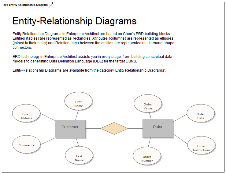
Entity Relationship Diagram | Enterprise Architect User Guide
UML Diagrams - Javatpoint The UML diagrams are categorized into structural diagrams, behavioral diagrams, and also interaction overview diagrams. The diagrams are hierarchically classified in the following figure: 1. Structural Diagrams. Structural diagrams depict a static view or structure of a system. It is widely used in the documentation of software architecture.

ER diagrams vs. EER diagrams: What's the difference? | Cacoo
Difference Between Data Flow Diagram (DFD) and UML ... Data Flow Diagram (DFD) vs UML . A graphical representation of how the data flows through a system is called a Data Flow Diagram (DFD). Developing a DFD is one of the first steps carried out when developing an information system. UML (Unified Modeling Language) is a modeling language used in object oriented software design.
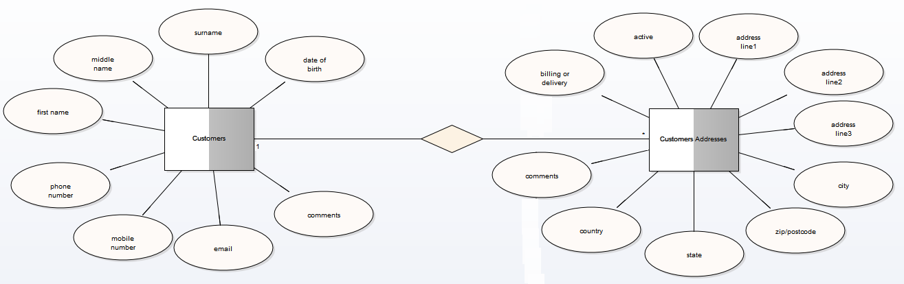
Entity Relationship Diagrams (ERDs) | Enterprise Architect ...
UML Diagram Tutorial: A Complete Guide to UML Diagrams Unified Modeling language (UML) Entity Relationship Diagram; Definition: UML diagrams represent the main objects used in software development, and allow visualization of these objects. This is also referred to as a blueprint for how an application will be built. In ER diagrams, the objects and their relationships are represented graphically. Relationships
3 Basic Data Modeling Techniques - ERD, UML and Data ...
UML vs. ER diagrams: A detailed comparison | Gleek The main difference between UML and ER diagrams is that UML is a language used to create diagrams, whereas ERDs are a type of diagram. UML is used for planning software development, and is used in many different diagrams for various purposes. ER diagrams do not focus on the software, but rather the modelling of databases, which are usually part of a software system. UML diagrams are broader, and have many uses, and ERDs only have one purpose.

How to Generate Class Diagram from ERD?
Entity Relationship Diagram Symbols | UML Class Diagram ... ERD symbols used for professional ERD drawing are collected in libraries from the Entity-Relationship Diagram (ERD) solution for ConceptDraw DIAGRAM. UML Class Diagram Notation When it comes to system construction, a class diagram is the most widely used diagram.

Software Engineering Lecture 10 UML vs. ERD. - ppt video ...
Difference Between ER Diagram and Class Diagram | Compare ... ER (entity-relationship) diagrams and Class diagrams are two of the design diagrams that the software developers create usually during the design phases of the software engineering life cycle. ER diagrams are a product of entity-relationship modeling (ERM) technique for modeling databases. A class diagram, written in Unified Modeling Language, is a diagram that describes the structure of a proposed system.

How to auto-create UML Class diagrams and ER diagrams ...
UML Association vs Aggregation vs Composition Generalization vs Inheritance. Generalization is the term that we use to denote abstraction of common properties into a base class in UML. The UML diagram's Generalization association is also known as Inheritance. When we implement Generalization in a programming language, it is often called Inheritance instead.

Convert UML to ER models - Astah
What is the Difference Between UML and ERD - Pediaa.Com The main difference between UML and ERD is that UML is a modeling language that represents a system or a software visually while ERD is a diagram that represents the entities and their relationships in a database. In brief, there are many diagrams in UML and, ERD itself is a UML diagram. References: 1."Basic Concepts of ER Model in DBMS."
Difference between UML and ERD | UML vs ERD

Data Flow Diagrams | Data Flow Diagram (DFD) | UML Class ...
What comes first, UML diagrams or ER diagrams? - Quora
Tutorial - Vorlesung: Modellierung in UML und ER
File:Difference between UML and ER diagram.jpg - Wikimedia ...

Guide to entity-relationship diagram notations & symbols | Gleek
GitHub - voormedia/rails-erd: Generate Entity-Relationship ...
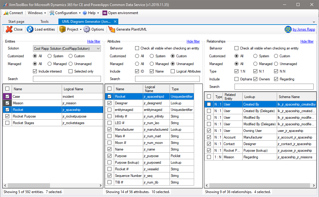
UML Diagram Generator for Microsoft Dynamics 365
ER Diagram and Class Diagram Synchronization - Object ...
How do we read cardinality in a UML diagram or in E/A diagram ...

Gleek Blog

ORDB Design Transforming a UML class diagram an ORDBM ...

Visual Paradigm vs Lucidchart | Lucidchart
20+ JavaScript libraries to draw your own diagrams (2022 edition)

The components of a Class Diagram and how it differs to ERD ...

How to edit Markdown + UML in Visual Studio Code
Entity Relationship Diagram - Data Modeling - UML Diagramming ...

mysql - Abstract Class from UML to ER diagram. Possible ? How ...
DBeaver Documentation

UML Paketdiagramme | Lucidchart
Difference between UML and ERD | UML vs ERD

UML 2 Class Diagram Guidelines
Data Modelling with UML - Training Material

Difference between UML and ER diagram - GeeksforGeeks

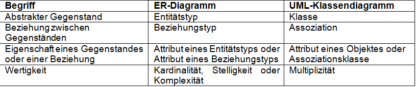
relationale Datenmodellierung: ER-Diagramm vs. UML-Klassendiagramm

UML Best Practice: 5 rules for better UML diagrams - Bellekens
Database Systems Design Part III : Entity-Relationship ...

UMLet - Free UML Tools for fast UML diagrams
Inner, Left, Right and Full Outer Join of Two Entities ...
Chapter 6 Database Design Using the ER Model
Text to UML and other "diagrams as code" tools - Fastest way ...
0 Response to "44 uml vs er diagram"
Post a Comment