45 crystal radio circuit diagram
How Does a Crystal Radio Set Work - Electronics Notes A typical crystal radio circuit is shown below and from this it can be seen how a crystal radio works. Basic crystal radio circuit . There are four main areas to the overall radio operation: Antenna / earth: Although the antenna / earth system is not actually part of the crystal radio, it is an essential element in seeing how the crystal radio ... Simplest AM Radio Circuit - Homemade Circuit Projects The circuit displayed below is a tunable AM signal trap circuit which can be controlled to retrieve unwanted AM signals and channel the remainder to the receiver. Inductor L1 is used as a broadcast loopstick-antenna coil whereas capacitor C1 is set for tuning. You can easily get these components from an old radio.
Make this Crystal Radio Set Circuit using No Batteries ... Crystal Radio Concept. The only downside of this radio concept is the requirement of a very long antenna and a deep earthing, therefore this unit is not something which you can carry in your pocket, nevertheless the extreme simplicity and the no power operation feature make this circuit an amazing device.
Crystal radio circuit diagram
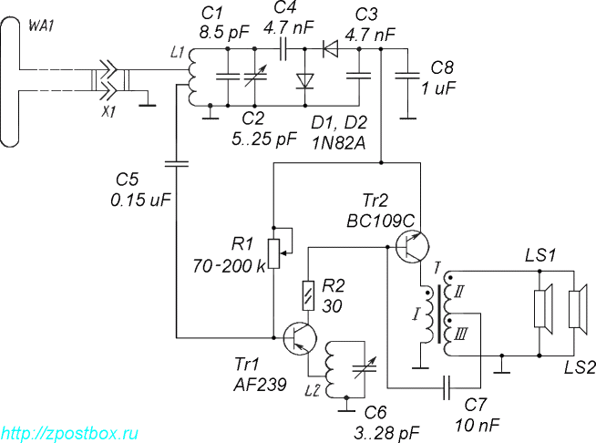
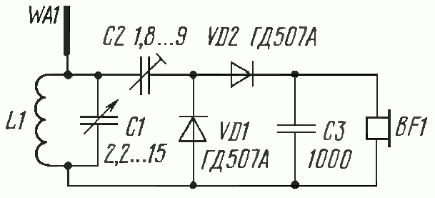
Dave's Homemade Radios Crystal Schematic Selector Crystal Radio Schematic Selector Page. Hi friends. I suppose that some of you have noticed that I built a lot of crystal radios. Some might say that is an understatement. The selecting of a radio that you might want to make for yourself sometimes starts with looking at the schematic diagram. PDF Crystal Oscillator Circuits Page 1 Crystal Oscillator Circuits - Page 5 Any general purpose NPN transistor can be used so long as it has an FT of above 100Mhz, well above the crystals fundamental frequency which is usually be between about 5MHz and 25MHz. The circuit diagram above of the Colpitts Crystal Oscillator circuit shows that capacitors, High-Power Crystal Radio Here's a pint-sized crystal radio with enough oomph to drive a 2 1/2" speaker. This units selectivity is far better than you would expect to find in a crystal receiver and volume is equal to that obtained with a transistor. No external power source is required. The unusual selectivity of this radio is due to its special double-tuned circuit.
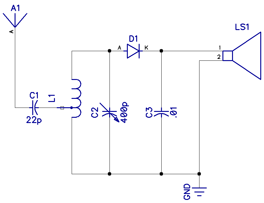
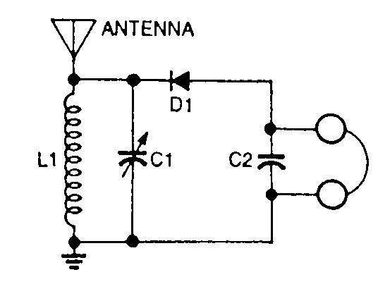
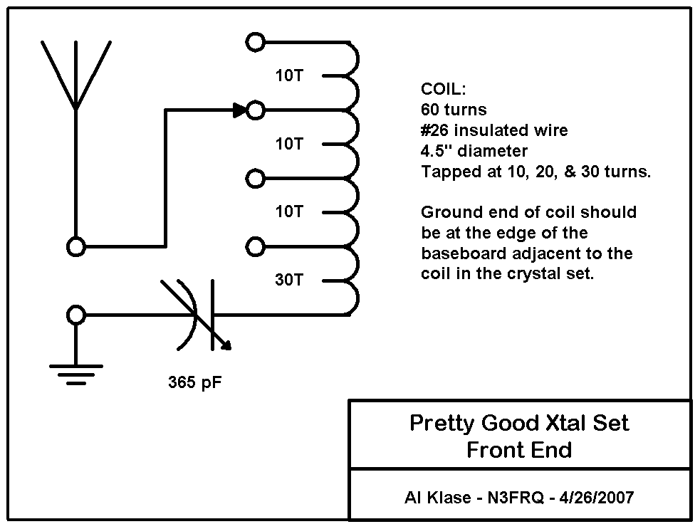
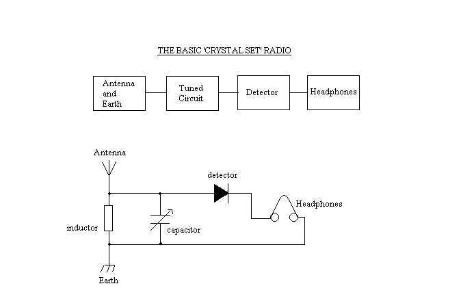
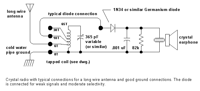
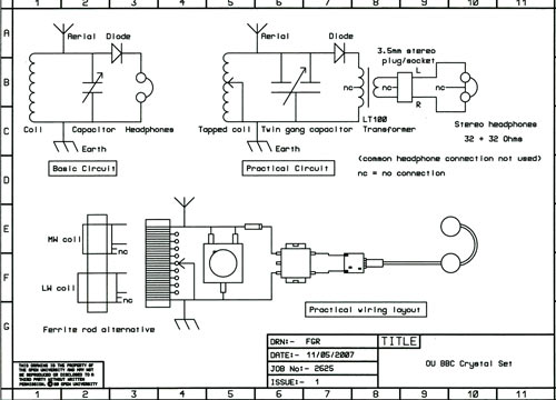
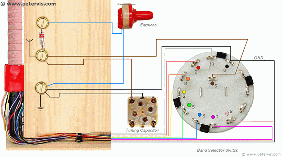
Crystal radio circuit diagram. Crystal Radio Schematic - U Wiring A typical circuit diagram for a Crystal Set Radio is given below where inductor or coil L1 is tuned by variable capacitor VC1 to the transmitter frequency. Want to make a radio. A crystal radio receiver also called a crystal set or cats whisker receiver is a very simple radio receiver popular. Crystal radio - Wikipedia Block diagram of a crystal radio receiver Circuit diagram of a simple crystal radio. A crystal radio can be thought of as a radio receiver reduced to its essentials. It consists of at least these components: An antenna in which electric currents are induced by radio waves. 8 Band Crystal Radio (Project Ultra) - Peter Vis The MW band is at around 45 turns of the coil, and the LW band is at around 100 turns of the coil. Circuit Diagram Please click on the image above to see the circuit diagram. Your task, should you choose to accept, is to make a new multi-band coil and test it using this crystal radio circuit diagram. Wiring Diagram Results Spy Crystal Radio - Peter Vis Circuit Diagram As you can see in this top-secret circuit diagram, the variable tuning capacitor connects across the taps in the coil. The taps are 15 turns from the antenna end, and 15 turns from the earthy side. There are 40 turns between the taps. This circuit is only for those who have a 300 pF variable tuning capacitor.
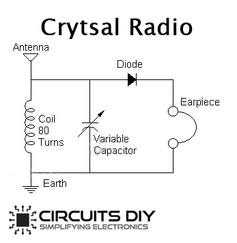
Tuggle Two - Crystal radio Crystal Radio web site. Crystal radio plans, crystal radio circuits, crystal radio schematics are all right here. Sound powered headphones and how to use them on crystal radios. Crystal Radios, Crystal Set, Crystal Sets, Catswiskers, Science Fair Crystal Radio, and much more! How to Make / Build a Crystal Radio - Circuits DIY After finishing the loop associate all parts like germanium diode, variable capacitor, coil and earpiece to make a crystal radio as appeared in the circuit diagram. After building the radio associate the longest receiving wire to the radio circuit and go outdoors to the window and attach it to any tree or simply put it out from the window. PDF CRYSTAL OSCILLATOR CIRCUITS - bgaudioclub.org Fig. 2.1. The traditional equivalent circuit using lumped constant ele-ments for the crystal is shown in Fig. 2.2. Inductance L, and series capacitance C, represent the crystal's frequency-sensitive elements. Capacitance C, is the capacitance between the two metallized surfaces used as electrode contacts on the crystal and runs about 3-15 pF ... Simple Oscillator Circuits - Making Easy Circuits Below diagram displays the circuit diagram of a simple CMOS crystal oscillator which usually relies on a couple of inverters. The two inverters widely-used to offer an amplifier which includes its input and output of the amplifier by way of TC1, and at the series resonant frequency of the crystal (where within the minimal impedance) optimistic ...
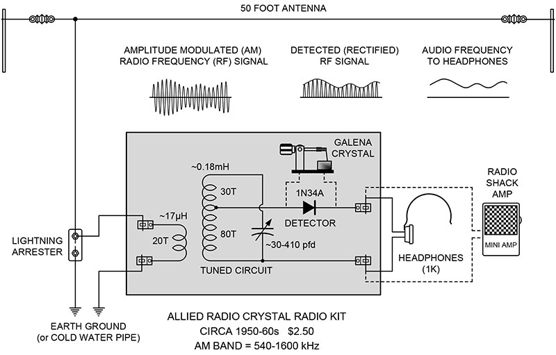
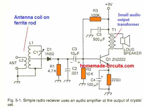
Crystal Radio Circuits -- 40 articles (pdf ) "Construction & Operation Of A Two-Circuit Radio Receiving Equipment With Crystal Detector" ( NBS Circular # 121, July 1922 ) "Oatmeal Box Crystal Radio" "Efficient Galena Receiver ( Hobby Mag., Spanish ) "Wide Range Bypass Crystal Tuner" ( Radio & Television News, Aug. 1949 ) "Reception With Galena" ( Spanish ) Crystal Radio Reciever with Amplifier - Circuits DIY Circuit Operation. The circuit appeared above is utilizing a transistor 2N3904 as a preamplifier and an IC LM386 which is amplifying the sound signals originating from transistor to drive a smaller than normal 8 ohms loudspeaker or earphones. Furthermore, this is a crystal radio speaker for enhancing the output sound to a crystal earphone or phone receiving earphones. Crystal Radio Most crystal radios use only one half of a radio frequency's wave. The importance of a good antenna and ground system. These radios are not connected to your house's AC power and they use no batteries. A crystal radio has no amplifying circuits and yet they output sound and sound is energy. Radio Circuits | Practical Analog Semiconductor Circuits ... For more crystal radio circuits, simple one-transistor radios, and more advanced low transistor count radios. Regency TR1: First mass produced transistor radio, 1954 . The circuit in the figure below is an integrated circuit AM radio containing all the active radio frequency circuitry within a single IC.
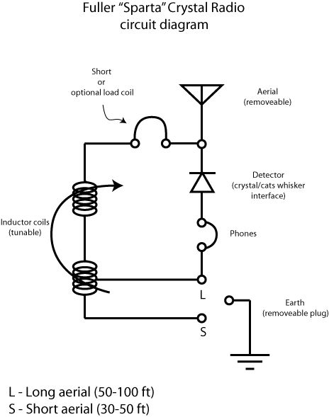
Sparta Crystal Radio - Physics Museum - The University of ...
Make A Crystal-Locked FM Transmitter | Full Circuit Project The circuit presented here uses a crystal oscillator and frequency multiplier to generate a highly-stable carrier signal frequency of 96MHz. With 40mW of RF output, it can be used to transmit voice or music up to hundred metres. The circuit diagram of the 96MHz crystal-locked simple FM transmitter is shown in Fig. 1.
How to Make / Build a Crystal Radio
Overview of Crystal Oscillator Circuit Working with ... Crystal Oscillator Circuit Diagram. The above figure is a 20psc New 16MHz Quartz Crystal Oscillator and it is one kind of crystal oscillators, that works with 16MHz frequency. Crystal Oscillator. Generally, bipolar transistors or FETs are used in the construction of Crystal oscillator
Crystal Radio circuit
Crystal Radio Circuits: Crystal Set Circuits » Electronics ... Crystal radio circuit with coil tapped to reduce loading on the tuned circuit. Although there is a reduction in loading on the coil, as only a proportion of the voltage that is developed across the coil is available for the detector and headphones the volume can be reduced. It can be a trade-off between volume and loading on the coil.

Crystal radio - Wikipedia
How to build a sensitive crystal receiver Circuit diagram 1 Circuit diagram of the crystal receiver, which we are going to design for maximum sensitivity at weak signals. This can be a detector circuit of a 2 circuit receiver. But also a receiver with loop antenna. RPrepresents the losses in coil L and tuner capacitor C1 Circuit diagram 2
Crystal Radio Circuits
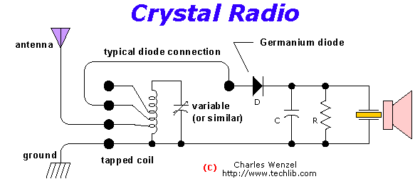
Crystal Radio Circuits - techlib.com The circuit is quite simple but many pitfalls await the novice. The first precaution is most important! The crystal radio works best with a long, high outdoor antenna but the beginner may not fully appreciate the danger of bringing such a wire into the house.

Crystal Radio with Amplifier | Circuit Diagram
How to make a batteryless (crystal set) radio ... What I was searching for is a small AM radio that I got in a box of cereal in the 50's. It had a button type earphone. Very small. All I had to do was to hook up 1 alligator clip to a ground, like a water pipe. Tuning was made with a small rod inside a tube. All you had to do was move the rod in or out till you got a station. Anybody remember ...
The "UnFETtered Crystal Radio! - circuit diagrams, schematics ...
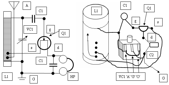
Jim's Crystal Radio Page - Hobby Tech schematic diagram of a basic crystal set. The tuned circuits in a crystal radio are composed of a coil (inductor) and a capacitor, usually variable, to allow tuning the circuit to the desired frequency. A crystal set can be made with a single tuned circuit (the detector coil), or with an added
How to Build an AM Radio Receiver - Circuit Basics
Crystal Radio Plans, Schematics, and Circuits Crystal Radio Plans and Circuits and parts of books This section contains 174 articles at the present time (articles are numbered) Many articles have multiple plans! Information Donated In Part By The Following Persons Mike Tuggle (Hawaii), Richard O'Neill, Lou Blasco, Mike Peebles, Andy Klute, Evan Haydon,
Tunable Crystal radio circuit under RF Receiver Circuits ...
Build a Crystal Shortwave Radio - antique radio Build a Crystal Shortwave Radio. This project combines two popular themes from radio history—crystal radios and shortwave (SW) listening. It's designed from scratch by our non-resident engineer Walter Heskes.. Despite all of the advances in modern electronics, there are thousands of crystal sets in daily use throughout the world.
FM crystal radio receivers - Optimization of a radio receiver ...
Build Your Own Crystal Radio | Science Project A crystal radio is a very simple radio that was popular in the early history of radios. It is an electrical circuit that can pick up and play sound from AM radio stations. Rather than rely on outside electrical sources, like a batteries or plugs, crystal radios get their power directly from the radio waves.
My Crystal Radio Page under Repository-circuits -42485- : Next.gr
Dave's Homemade Crystal Radio Projects and Plans Main Page. Want to make a radio? Welcome to Dave Schmarder's 78 homemade crystal radio receiver projects with plans and schematic diagrams. I show very simple crystal sets, as well as high performance radios with holy grail parts. All crystal radio plans are shown. Others have made these into detector radio kits. Litz wire is often used.

Jim
High-Power Crystal Radio Here's a pint-sized crystal radio with enough oomph to drive a 2 1/2" speaker. This units selectivity is far better than you would expect to find in a crystal receiver and volume is equal to that obtained with a transistor. No external power source is required. The unusual selectivity of this radio is due to its special double-tuned circuit.

Nic Nac Tic Tac Crystal Radio Set - an Ideal Primary School ...
PDF Crystal Oscillator Circuits Page 1 Crystal Oscillator Circuits - Page 5 Any general purpose NPN transistor can be used so long as it has an FT of above 100Mhz, well above the crystals fundamental frequency which is usually be between about 5MHz and 25MHz. The circuit diagram above of the Colpitts Crystal Oscillator circuit shows that capacitors,

Dave's Homemade Radios Crystal Schematic Selector | Radio ...
Dave's Homemade Radios Crystal Schematic Selector Crystal Radio Schematic Selector Page. Hi friends. I suppose that some of you have noticed that I built a lot of crystal radios. Some might say that is an understatement. The selecting of a radio that you might want to make for yourself sometimes starts with looking at the schematic diagram.
Crystal Radio Circuits

Build Your Own Crystal Radio | Science Project
xtal
Amplifier for crystal radio earphone

A Simple Radio Receiver
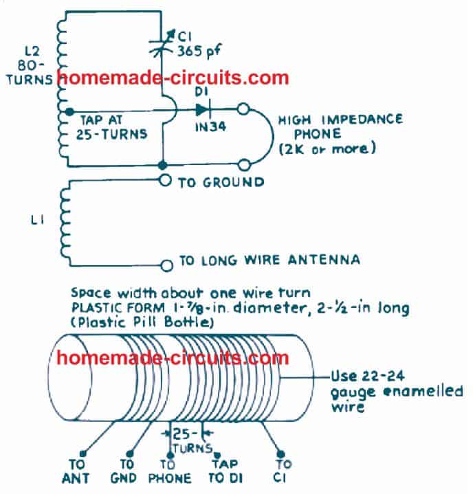
Make this Crystal Radio Set Circuit using No Batteries ...

Crystal radio Facts for Kids

Dave Schmarder's #2 Crystal Radio New Schematic | Radio ...

kjs crystal radio, bbc

Crystal Radio Circuits: Crystal Set Circuits » Electronics Notes

A Crystal Set - Verulam Amateur Radio Club : Verulam Amateur ...

3D Printed FM Crystal Radio

Crystal Radio Schematic | Radio, Shortwave radio, Electronics ...

Antique Radio Forums • View topic - Crystal set construction ...

Pin on Ham Radio
The Creative Science Centre - by Dr Jonathan P. Hare
Crystal Radio Circuits
Remembering the Crystal Radio | Nuts & Volts Magazine
FM Crystal Radio Receivers

File:Circuit diagram of a crystal radio receiver.svg ...
Make this Crystal Radio Set Circuit using No Batteries ...
Building a crystal radio set - OpenLearn - Open University

Crystal Radio Schematic | Radio, Electronic circuit projects ...
8 Band Crystal Radio (Project Ultra)

Dave's Homemade Radios Crystal Schematic Selector Page 2 ...
Crystal Radio Circuits

Radio Circuits | Practical Analog Semiconductor Circuits ...
FM Crystal Radio Circuit

How a Crystal Radio Works

File:Common crystal radio circuit.svg - Wikimedia Commons
First Radio
0 Response to "45 crystal radio circuit diagram"
Post a Comment