45 ph diagram for refrigeration cycle
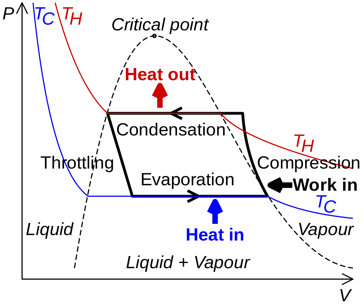
REFRIGERATION Mechanical refrigeration processes, of which the vapor compression cycle is an example, belong to the general class of reversed heat engine cycles, Figure 1.This figure represents, schematically, the extraction of heat at rate from a cold body at temperature T C.The process requires the expenditure of work W and the sum is discharged at a higher temperature T H. Celebrities Archives - Hollywood.com Click to get the latest Celebrities content. Sign up for your weekly dose of feel-good entertainment and movie content!
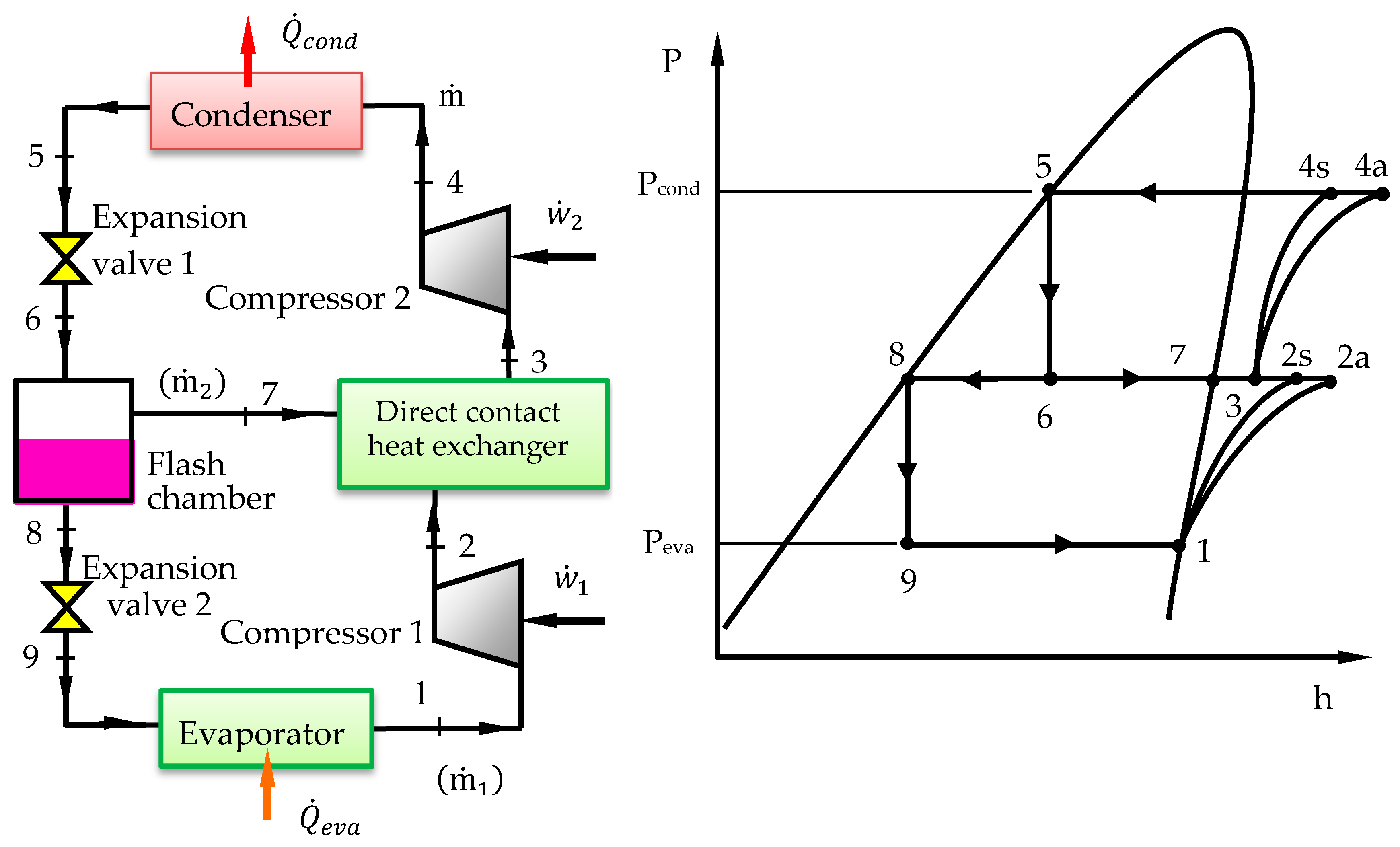
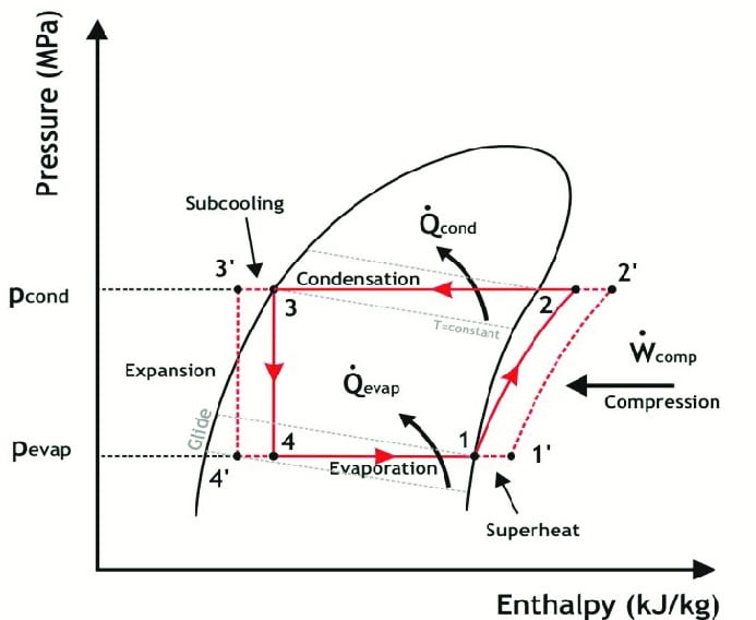
2.4 The complex cycle in a log Ph diagram - SWEP Figure 2.9 The real refrigerant cycle in the log P/h diagram. The overheating is the difference between the temperatures at points 1.1 and 1.2. The sub-cooling is the difference between the temperatures at points 3.1 and 3.2. Figure 2.10 Log P/h diagram with temperature levels shown. Figure 2.11 The energy flow in a refrigerant system.

Ph diagram for refrigeration cycle
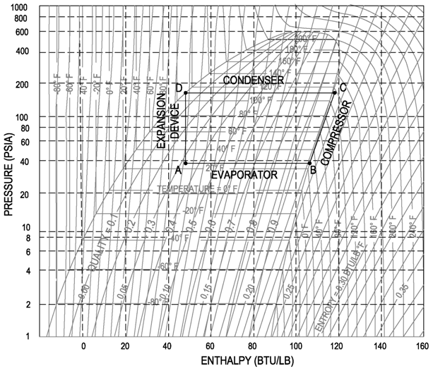
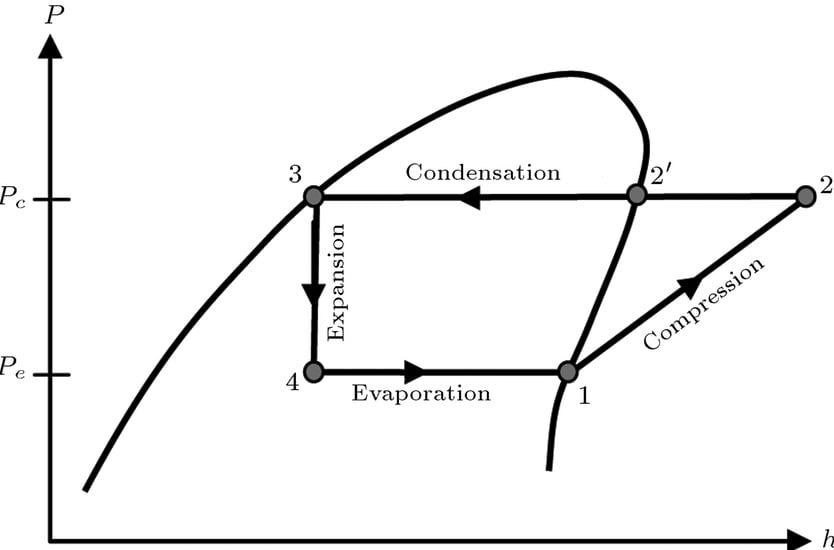
Refrigeration - Cycle for Ideal conditions on a Pressure ... Learn how to draw a cycle for ideal conditions on a PH chart.Please provide feedback on this module by selecting "Like" or "Dislike". Your feedback and comme... Ideal refrigeration cycle P-h diagram; 1→2: isobaric ... Download scientific diagram | Ideal refrigeration cycle P-h diagram; 1→2: isobaric cooling and isothermal/isobaric condensation; 2→3: isenthalpic expansion; 3→4: isobaric/isothermal ... Hot Gas Bypass (HGBP) and the Pressure Enthalpy Diagram ... 06/03/2018 · The design cycle has a refrigeration effect of 61 Btu/pound of refrigerant. The 12,000 Btu/hour design divided 60 minutes, is 200 Btu/minute. Divide 200 by 61, and the mass flow of refrigerant per minute is 3.28 pound per minute. This is the design flow rate. The flow at low load depends on the volume change of the refrigerant at the compressor inlet. For the …
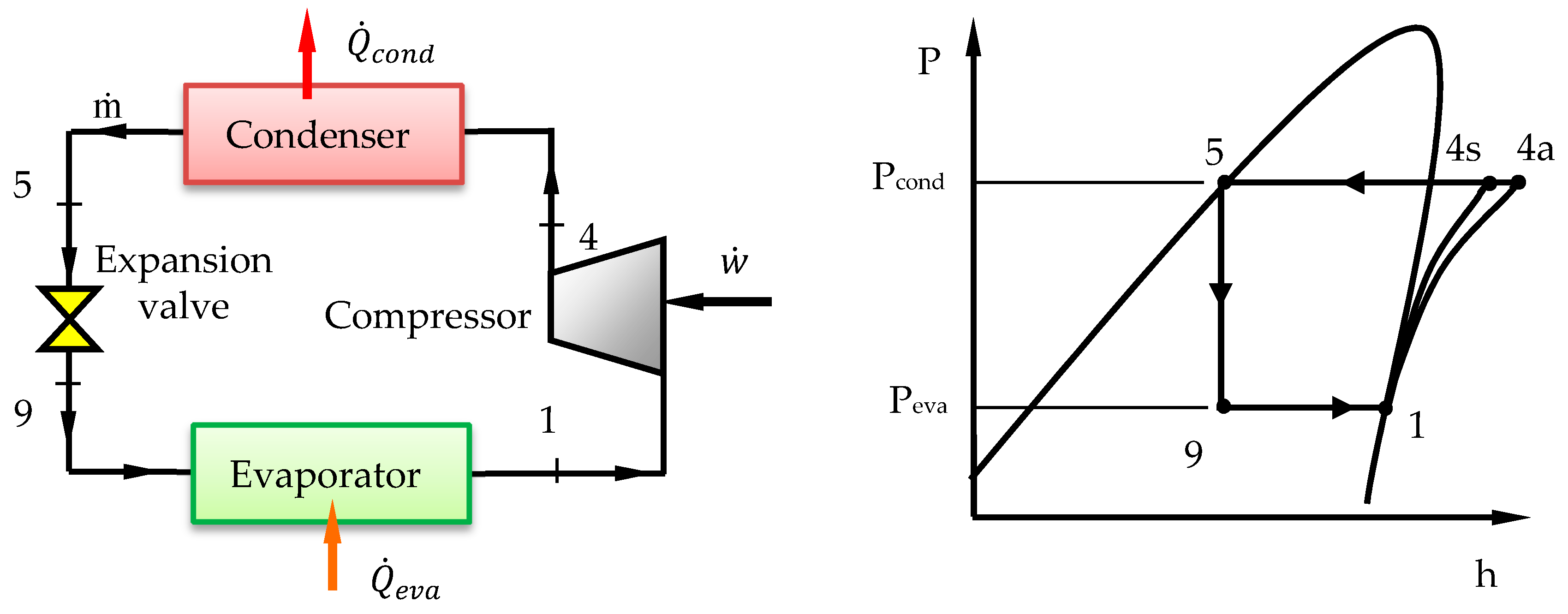
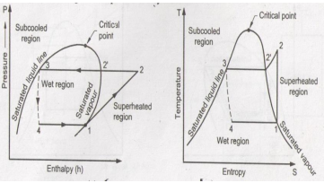
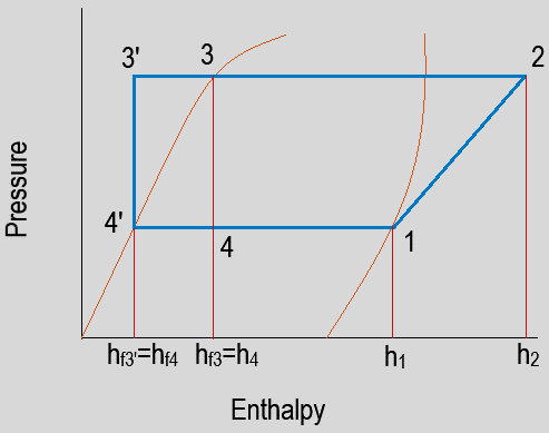
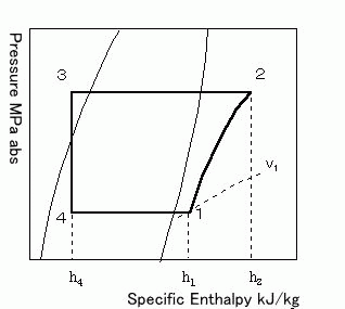
Ph diagram for refrigeration cycle. 2.3 The basic cycle in a log Ph diagram - SWEP 2.3 The basic cycle in a log Ph diagram Navigation Figure 2.8 shows the fundamental process that describes the ideal refrigeration cycle. The following are assumed for the fundamental process: No sub-cooling of the liquid or superheating of the gas Ideal compression, i.e. it occurs at constant entropy No pressure drop losses PDF UNIT 2 REFRIGERATION CYCLE Refrigeration Cycle Refrigeration cycle is the basis of all refrigeration systems. So refrigeration cycle should be known to understand the refrigeration system. Some basic refrigeration cycles are discussed here through different diagrams. 2.2 VAPOUR COMPRESSION CYCLE Vapour compression cycle is an improved type of air refrigeration cycle in which a suitable ... PDF Refrigeration Cycle - Landmark University Fig. 11. T-S diagram for Wet Vapour Compression Cycle Fig. 12. P-h diagram for Wet Vapour Compression Cycle In this cycle, enthalpy at state 2 is found with the help of dryness fraction at this point (2). The dryness fraction at points 1 and 2 may be obtained by equating entropies at state 1 and 2. C.O.P = = JSRAE, Japanese Society for Refrigerating and ... A p-h diagram is a figure with a vertical axis of absolute pressure and a horizontal axis of specific enthalpy. It is an important diagram used frequently for a performance calculation of a refrigerating machine. A p-h diagram is made respectively for a specified refrigerant. It can, of course, not be used for another refrigerant.
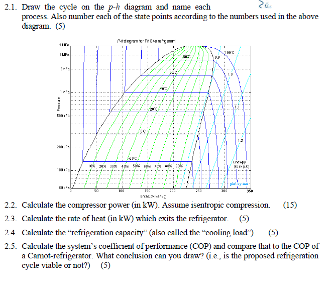
PDF Case 1: The Basics of Refrigeration Cycle P.H. Diagram ... Figure 1-6 Refrigeration Cycle P-H Diagram Image Figure 1-7 Properties of Refrigerant at -20℉ Figure 1-8 Properties of the Refrigerant at 105℉ H 1is the saturated suction of the compressor at -20ºF. at no losses. H 2is the compressor discharge point at no losses. H 5is the saturated liquid at 105ºF condensing temperature. 2.1 The pressure-enthalpy diagram - SWEP Refrigeration handbook 1. Basic heat transfer 2. Compression cycle 2.1 The pressure-enthalpy diagram; 2.2 Basic components; 2.3 The basic cycle in a log Ph diagram; 2.4 The complex cycle in a log Ph diagram; 2.5 Other components; 3. Compressors 4. Expansion valves 5. Refrigerants 6. Evaporators 7. Condensers 8. Practical advice PDF Ph diagram for refrigeration cycle Ph diagram for refrigeration cycle Continue Ph diagram for refrigeration cycle Efficiency - Working with the Refrigerant Circuit To measure what is happening the first thing to do is to find the temperatures and pressures at key points in the circuit. Measurement points for Temperature T and Pressure P can be used to define the process. Rosemount | Emerson US Emerson's tireless pursuit of innovation drives the Rosemount™ portfolio of superior quality measurement and analytical technologies to provide customers with insight across all touch points needed to operate efficiently, safely, and with peace of mind.
Continuous electrochemical refrigeration based on the ... 10/02/2022 · In this work, we conceptualize an electrochemical refrigeration cycle and demonstrate a proof-of-concept prototype in continuous operation. The refrigerator is based on the Brayton cycle and draws ... Refrigerant Ph Diagram - Heat Exchangers - Brewiki The optimum intermediate pressure for the two-stage refrigeration cycles is determined as the geometric mean between evaporation pressure (p {) and condensing pressure (ph, Fig. 11-79): based on equal pressure ratios for low- and high-stage compressors. PDF How does basic refrigeration cycle work? If you are interested in learning how a refrigeration system works, it is helpful to understand from the Ph (Pressure Enthalpy) chart perspective. It makes our life much easier. This is how the refrigeration cycle diagram looks: Yeah, it seems complicated at first, but it will be easier to understand once I have explained the refrigeration ... PDF Chapter - 2 - Industrial refrigeration systems P-H Diagram is to analysis the feasibility of the refrigeration cycle, to calculate the thermodynamic properties of the refrigeration system. Use the P-H Diagram analysis, all the refrigerant flow rates and operating conditions at the design point for the system can be clearly determined. (2) Refrigerant Flow Diagram.
Rankine Cycle - an overview | ScienceDirect Topics The schematic flow diagram in Fig. 30 depicts how the cycle is conducted. The geofluid after being pumped from the reservoir is used solely for its heat energy. It passes through a series of heat exchangers, and is then reinjected back into the reservoir. The geofluid never comes into contact with the surface environment. The heat extracted from the geofluid is used to …
Refrigeration Basics and LNG - University of Oklahoma Figure 2-4: Wet refrigeration Cycle - The expander has been substituted by a throttling valve. If an expander had been used the line from d to a would be a vertical line. This is also done for mechanical reasons. The refrigeration cycles can also be represented in a P-H diagram. Figure 2-5: P-H diagram representation of a dry refrigeration cycle
What is Refrigeration Cycle? Basic, Diagram & Explanation ... The refrigeration cycle is a thermodynamic cycle to generate refrigerating effect with the use of an evaporator, compressor, condenser & expansion valve. This process is basically a thermodynamic process where working fluid absorbs heat from the surrounding at low temperature and reject the heat to the atmosphere at a higher temperature.
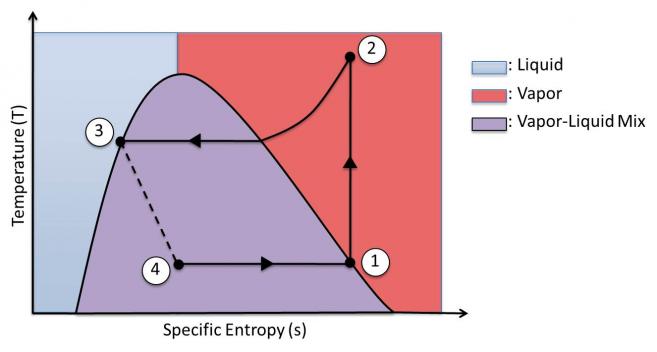
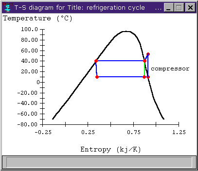
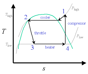
PDF Basic Knowledge Thermodynamics of the Refrigeration Cycle The log p-h diagram for refrigerant The refrigeration cycle For operating media which can have different phases, such as water or refrigerant, theT-sdiagram looks different. It has an area on the left (grey),in which the operating medium is liquid and supercooled. In the centre(blue) there is a mixture of steam and liquid, the wet steam.
Rankine cycle - Wikipedia The Rankine cycle is an idealized thermodynamic cycle describing the process by which certain heat engines, such as steam turbines or reciprocating steam engines, allow mechanical work to be extracted from a fluid as it moves between a heat source and heat sink. The Rankine cycle is named after William John Macquorn Rankine, a Scottish polymath professor at Glasgow …
REFRIGERATION AND AIR CONDITIONING THIRD ... - … REFRIGERATION AND AIR CONDITIONING THIRD EDITION. रघुबेन्द्र सिंह . Johana C Siliwire. Download Download PDF. Full PDF Package Download Full PDF Package. This Paper. A short summary of this paper. 37 Full PDFs related to this paper. Read Paper. Download Download PDF. Download Full PDF Package ...
PDF Chapter 10: Refrigeration Cycles - Saylor Academy The P-h diagram is another convenient diagram often used to illustrate the refrigeration cycle. The ordinary household refrigerator is a good example of the application of this cycle. Results of First and Second Law Analysis for Steady-Flow Component Process First Law Result Compressor s = const. Wmhh () in =−21
P-H Diagram, Pressure Enthalpy Diagram for Refrigeration ... In this video we explain the importance of the P-H diagram and how useful this is for the refrigeration cycle. Gauge and absolute pressure is also explained ...
Log ph diagram online I TLK Energy Representation of a refrigeration cycle. In our interactive log ph diagram, refrigeration cycles can be parameterized in different ways. For a simple refrigeration cycle, we offer the possibility to specify either the evaporating and condensing pressure or the evaporating and condensing temperature.
PDF Refrigeration - NCSU P-H Diagram for Ideal Conditions e . H 1 = h f based on temperature at 'd' (exit of condenser) H 2 = h g based on temperature at 'a' (exit of evaporator) Note 1: If there is super-heating in the evaporator, H 2 can not be obtained from P-H table Note 2: If there is sub-cooling in the condenser, H 1 can not be obtained from P-H table
Explain vapour compression refrigeration cycle on T-S and ... Vapour Compression Refrigeration Cycle. The P-H and T-S diagram for the simple vapor compression refrigeration cycle is shown in the figure for vapour entering the compressor is in dry saturation condition The dry and saturated vapour entering the compressor at point 1 that vapour compresses isentropic ally from point 1 to 2 which increases the pressure from evaporator pressure to condenser ...
Seawater - Wikipedia Seawater, or salt water, is water from a sea or ocean.On average, seawater in the world's oceans has a salinity of about 3.5% (35 g/l, 35 ppt, 600 mM). This means that every kilogram (roughly one liter by volume) of seawater has approximately 35 grams (1.2 oz) of dissolved salts (predominantly sodium (Na +
PDF Thermodynamics of the refrigeration cycle gunt The refrigeration cycle in the log p-h diagram The distinctive feature of the refrigeration cycle is that it runs counter-clockwise, i.e. opposite to the joule or steam cycle. A change of state occurs when the refrigerant fl ows through one of the four main components of the refrigeration plant. The
P-h diagram of vapor compression refrigeration cycle ... The vapor compression refrigeration cycle consists of four processes: (1-2) compressing refrigerant in compressor isentropically, (2-3) condensation at constant pressure, (3-4) adiabatic expansion...
PDF Refrigeration Cycle Tutorial - University of Oklahoma The refrigeration cycles can also be represented in a P-H diagram. Figure 5: P-H diagram representation of a dry refrigeration cycle Refrigerant fluid choice: We now turn our attention to the fluids. Usually, one tends to pick pL as low as possible, but not below atmospheric pressure. Thus, the refrigerant chosen needs to have a normal boiling ...
CO2 Transcritical Systems Training Manual 042718 R22 P/H Diagram * Diagram created using REFPROP – NIST Reference Fluid Properties As can be seen, the critical point of R-22 is more than 200°F, placing it well above the operating conditions of typical refrigeration systems. This can be contrasted with the CO 2 PH diagram, with a critical point of 88°F. This temperature is often exceeded ...
Maintenance Training Webinars | HD Supply • Air Conditioning 101 - The Refrigeration Cycle (6.5 Hours): Learn the concepts of pressure, temperature relationship, heat, and vapor compression. Cost: $99 • Air Conditioning 102 - Refrigerants And Oils (6.5 Hours): This introductory course covers refrigerant, oils, and retrofitting.
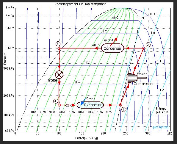
Refrigeration cycle diagram explained - Refrigeration ... Refrigeration cycle in the log p-h diagram Green = compressor Red = condenser Yellow = expansion valve Blue = evaporator 1 - 2 polytropic compression to the condensing pressure (for comparison 1 - 2' isentropic compression) 2 - 2'' isobaric cooling, deheating of the superheated vapour 2'' - 3' isobaric condensation
PDF Refrigeration Cycle - Simon Fraser University M. Bahrami ENSC 461 (S 11) Refrigeration Cycle 3 Fig. 5-3: T-s and P-h diagrams for an ideal vapor-compression refrigeration cycle. 1-2: A reversible, adiabatic (isentropic) compression of the refrigerant. The saturated vapor at state 1 is superheated to state 2. wc =h2 − h1
P-h Chart for R134a (SI Units) - Syracuse University Reversed Carnot Cycle s T T C T H. 4 0.0 5.0 10.0 15.0 20.0 25.0 30.0-40.0 -35.0 -30.0 -25.0 -20.0 -15.0 -10.0 -5.0 0.0 5.0 10.0 Cold-Side Temperature - T C, C COP c 20.0 30.0 40.0 50.0 60.0 70.0 Carnot Cycle Performance Sat Cond T, °C Reversed Carnot Vapor Compression Cycle s T T C T H. 5 Reversed Rankine Vapor Compression Cycle s T T C T H Superheat Horn …
Hot Gas Bypass (HGBP) and the Pressure Enthalpy Diagram ... 06/03/2018 · The design cycle has a refrigeration effect of 61 Btu/pound of refrigerant. The 12,000 Btu/hour design divided 60 minutes, is 200 Btu/minute. Divide 200 by 61, and the mass flow of refrigerant per minute is 3.28 pound per minute. This is the design flow rate. The flow at low load depends on the volume change of the refrigerant at the compressor inlet. For the …
Ideal refrigeration cycle P-h diagram; 1→2: isobaric ... Download scientific diagram | Ideal refrigeration cycle P-h diagram; 1→2: isobaric cooling and isothermal/isobaric condensation; 2→3: isenthalpic expansion; 3→4: isobaric/isothermal ...
Refrigeration - Cycle for Ideal conditions on a Pressure ... Learn how to draw a cycle for ideal conditions on a PH chart.Please provide feedback on this module by selecting "Like" or "Dislike". Your feedback and comme...



















0 Response to "45 ph diagram for refrigeration cycle"
Post a Comment