45 water pump installation diagram
Water Pump Manuals and User Guides — All-Guides.com This section is dedicated to Water Pump manuals & user guides which are included in the main list of categories. The page provides a catalogue of brands and devices, each offering to view or download an updated manual. To see the entire list of Water Pump items designed by a particular manufacturer click on 'More' button. PDF Booster Pump Installation Instructions Booster Pump Installation Instructions 1. Install pressure switch in tank line. (See diagram on back for where to place the pressure switch). 2. Pump must be located within 2 feet of pressure switch and within 6 feet of power outlet. A. Pump can be mounted to the wall horizontally in either direction or vertically only one way ~ with pump head and
PDF aquatec Permeate Pump Installation ... - Pure Water Products Permeate Pump decreases the time to fill the tank, but it does not reduce the amount of water produced. For manifold type RO systems, contact the factory for installation recommendations. Technical Specifications Part number: ERP 1000 Pump Type: Positive displacement, reciprocating, single action diaphragm, hydraulically driven Weight: 1 lb.

Water pump installation diagram
THE TYPICAL PUMP INSTALLATION SET UP - The Process ... So the complete Typical Pump Installation Setup For A Centrifugal Pump is shown in the below schematic: The flow to this Centrifugal Pump goes from Tank → Suction Gate Valve → Pipe Diameter Reducer → Pump Suction/Pump Discharge → Pipe Diameter Expansion → Check Valve → Discharge Gate Valve → Distribution Header Pipe Pool Plumbing Diagram & Layout Schematic Examples Be sure to carefully analyze your swimming pool pump and filter installation diagram before creating any permanent seals. Water. Water is the central element that keeps everything in your swimming pool - systems and equipment - in excellent working order. Keep water level well-topped up to protect the spa combination plumbing equipment. Water Pump Installation Diagram Needed: Someone Else Took ... Install the water pump with a new gasket. Install a 135.5 mm stud at location No. 5 and tighten to 7 Nm (62 inch lbs.). Install a 137 mm stud at locations No. 4, 6, 7 and 8, and tighten to 7 Nm (62 inch lbs.). Install the water pump with a new gasket. Tighten the nuts and bolts in the sequence shown.
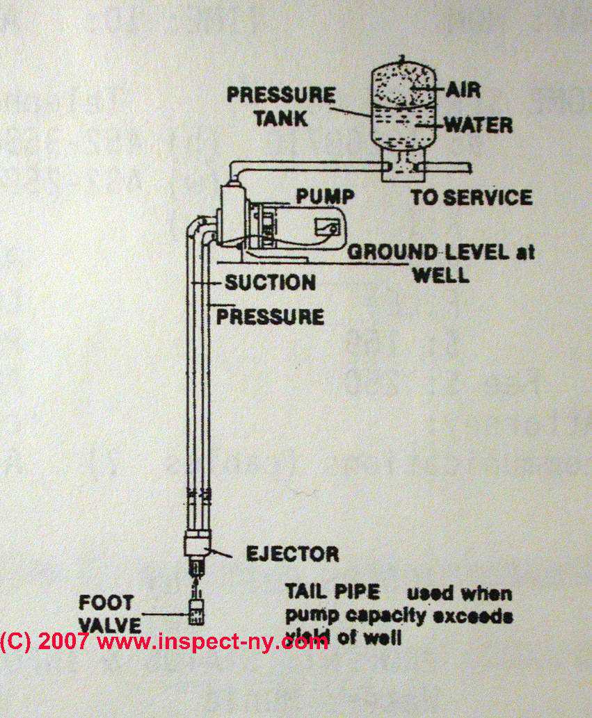
Water pump installation diagram. Deep Well Pump Installation Diagram | Deep well pump, Well ... Jet Pump. Centrifugal Pump. Drain Pump. Oil And Gas. Diagram. Wellness. Infographics: Single Stage Deepwell Cargo Pump. Deepwell cargo pumps are electrically driven cargo discharge pumps which are now used in place of Cargo Operated Pump Turbine (COPT) on tanker ships. Learn about the different parts of the pump in this infographics. How Does Hot Water Recirculation Pump Work? #Diagram ... The water pump used in the hot water recirculating pump is ideally of a softball size. It is generally installed above the water heater or just below the sink. In most of the cases, installation above the heater has been rated to be one of the excellent options. PDF INSTALLATION AND OWNER'S MANUAL - Dab Pumps OF INSTRUCTIONS BEFORE PROCEEDING WITH INSTALLATION INSTALLATION DIAGRAM - SURFACE PUMPS ELECTRICAL CONNECTIONS NOT SHOWN ON THIS DIAGRAM. UNIT MAY BE MOUNTED DIRECTLY ON THE SURFACE PUMP OR BETWEEN THE PUMP AND THE FIRST TAP. 17 Remove pressure switch from surface pump and wire Mascontrol directly to pump.® IMPORTANT PDF Typical Shallow Well Jet Pump Installation TYPICAL DEEP WELL JET PUMP INSTALLATION a captive air Jet pumps usually come with a 30-50 pressure switch factory installed on the pump. If replacing the switch we recommend using one with a 30-5 psi setting. 1. Deep well jet systems are used when the water depth is between 20' and 80'. For wells deeper than 80' a submersible pump system ...
How to Install and Wire a Well Pump - Water Pumps Direct Before Installation. Well pump installation can be dangerous when dealing with water and electricity, so extreme caution must be taken. Before getting started, look up your owner's manual and read over the precautions and all other warnings before beginning the installation. The manual will contain important safety precautions, wiring diagrams, tools required for assembly, proper grounding ... RV Fresh Water System Diagram | Plumbing Schematic Water Pump - The Heart of the Plumbing System. The water pump pressurizes the water lines, much like a heart to the circulatory system. It is located just outside of the fresh water tank, where it pulls the water through itself and into the water main. The 12-volt water pump should be turned off when you aren't going to be near the RV. PDF Application, Selection & Installation Guide - TACO Mount the valve under the sink and the pump at the water heater. The valve's unique thermal disk technology sends cooled water back to the water heater so hot water lines remain hot. Cleaning made easy. There's no need to remove the Hot-Link valve from the piping to keep it clean. Our exclusive clean-in-place design makes short Water Pump Setup Diagram - U Wiring Submersible Pump Control Box Wiring Diagram For 3 Wire Single Phase Submersible Pump Submersible Electrical Circuit Diagram. Automatic Water Level Controller Wiring Diagram For 3 Phase Motor Submersible Pump Water Pump Motor Submersible Pump Electrical Installation. Booster Pump Explain New 2017 Youtube Well Pump Refrigeration And Air ...
Installing A Campervan Water System [Sink & Plumbing Diagrams] This DIY guide to installing a campervan water system will show you how to install an RV hand sink pump, foot sink pump and 12V electric sink pump. Learn how to set up your water tank, run plumbing and collect waste water. Simple, easy to read instructions on 12 volt systems and example RV installation. WATER PUMP INSTALLATION WORKS!! - YouTube We're doing the plumbing on a new house and well, the water pump installation works which makes me very happy. It's good for heights up to 36M and my roof is... PDF JET PUMP INSTALLATION - National Pump Company 1 1/4" holes are full of water. STEP 5 Mount the pump onto the well adapter with gaskets and bolts, making sure that the 1 1/4" and 1" holes in pump line up with the holes in th e adapter. STEP 6 Prime the pump by pouring water into the discharge of the pump housing or automatic regulator mounted in discharge of the pump on some models. Submersible Well Pump Accessories Installation Diagram Home > Technical Information > Pumps Technical Data > Submersible Well Pump Technical Data > Submersible Well Pump Accessories Installation Diagram This illustration is for educational purposes It is not intended as an installation guide.
Chilled Water Pump Connection Details with Explanation ...
Water-Powered Backup Sump Pumps: Ultimate Guide The diagram below illustrates a basic Water Commander ™ water-powered sump pump installation common in many homes. The pump has to be connected to your home's water supply, generally a 3/4″ or 1″ line. A suction pipe descends from the pump into the sump pit, while a discharge pipe brings the water out of the home. ...

Conventional Pump & Pressure Tank Installation Diagram ...
PDF Tankless Water Heater Installation Diagrams INSTALLATION DIAGRAMS Rheem Water Heating ATTN: Tankless Business Unit 2600 Gunter Park Drive East Montgomery, AL 36109-1413 Office: 334-260-4692. Hot Water to Fixtures Gas Pipe Cold Water Pipe Hot Water Pipe Union Return Circulation Line Shut-off Valve Circulation Pump Pressure Relief Valve Check Valve Cold Water Isolator Valve Assembly Hot ...
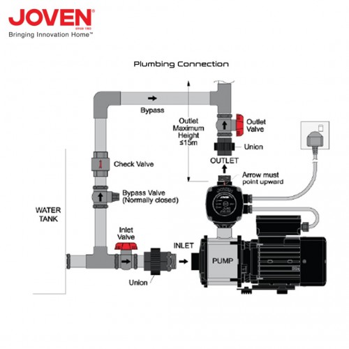
Joven JHP3-40 JHP Series Automatic Domestic Water Pump 0.55KW/0.75HP
How a Well Pressure Tank Works - with Diagrams - Plumbing ... Water Pressure Tank Installation Diagram. The image below shows the typical installation diagram of a well pressure tank, as well as other components of a well system. Image: Lakeland Water Pump How a Bladder Pressure Tank Works. A bladder pressure tank is a steel tank with a bladder inside which looks like a balloon.

Recirculation Pump Installation and Repair in Saddle Brook, NJ
Diagrams --Typical Pump Installations - Water Pump Supply Diagrams --Typical Pump Installations. The information provided here is for educational purposes only. Technically qualified personnel should install pumps and motors. We recommend that a licensed contractor install all new systems and replace existing pumps and motors. Failure to install in compliance with local and national codes and ...
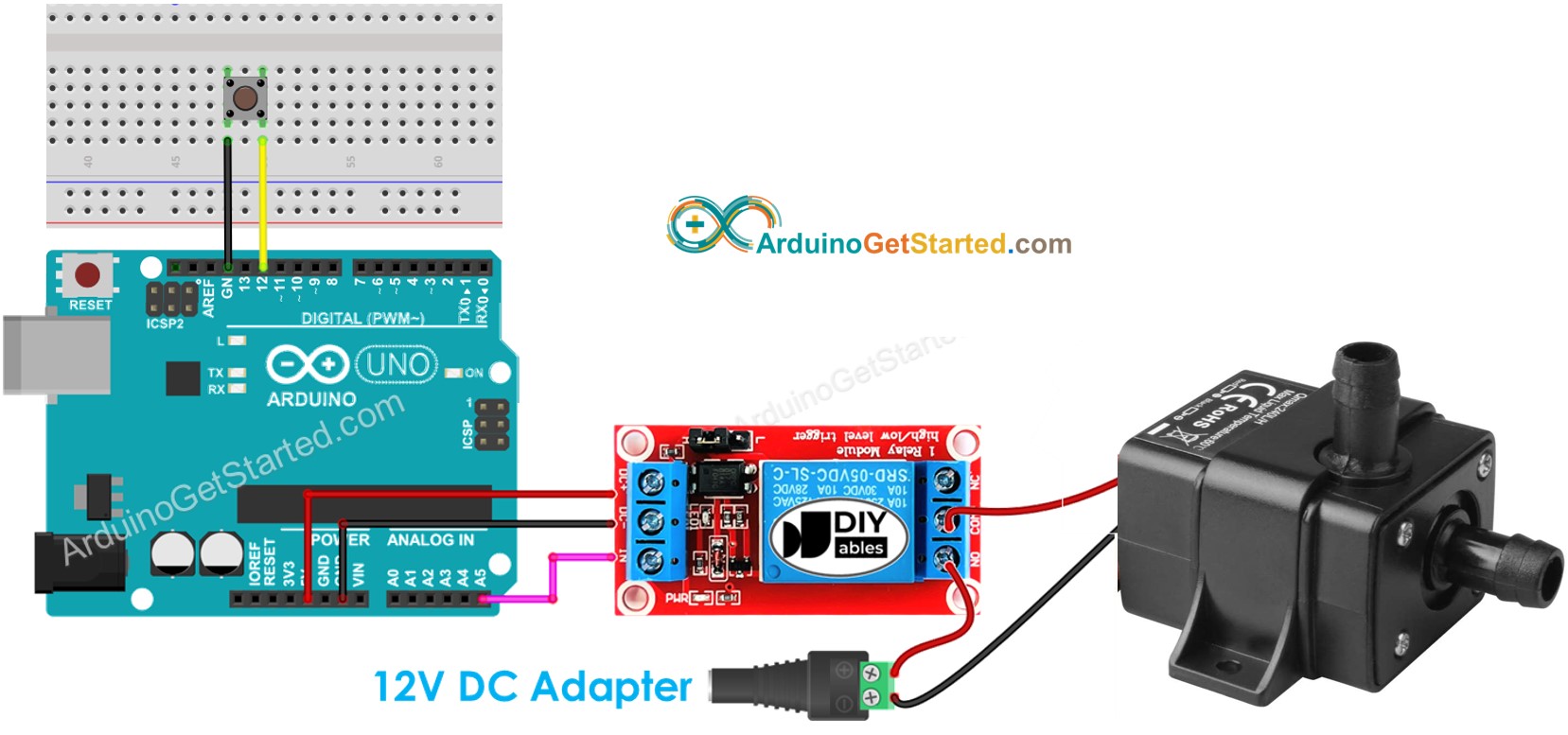
Arduino - Button - Pump | Arduino Tutorial
PDF TYPICAL SUBMERSIBLE PUMP INSTALLATION - Grover Electric Prevents surface water from seeping around casing into potable water. 11. Threaded and coupled galvanized pipe should be used on extremely deep wells. Threaded schedule 80 PVC and a heavy grade poly pipe are also available and are much lighter and easier to work with. 12. Position a torque arrestor directly above the top of the pump.

Install Whole House Pumps | How To Pages
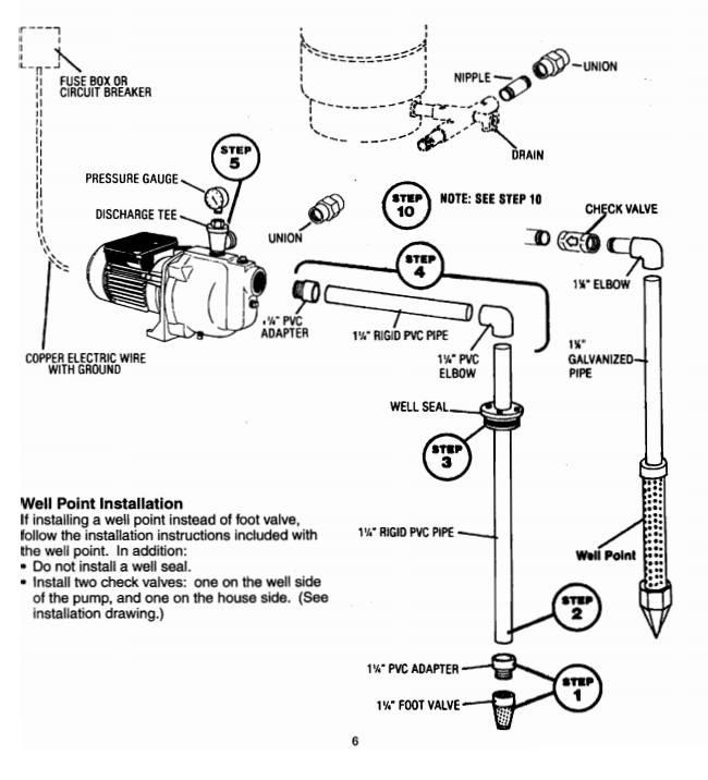
PDF Installation Manual DIAPHRAGM WELL TANK - American Water TYPICAL JET PUMP INSTALLATION Thread one end of 1/4" X 3" brass nipple into bottom of pressure switch. Thread other end into left 1/4" hole of tank cross. Thread pressure gauge into right 1/4" hole of tank cross.
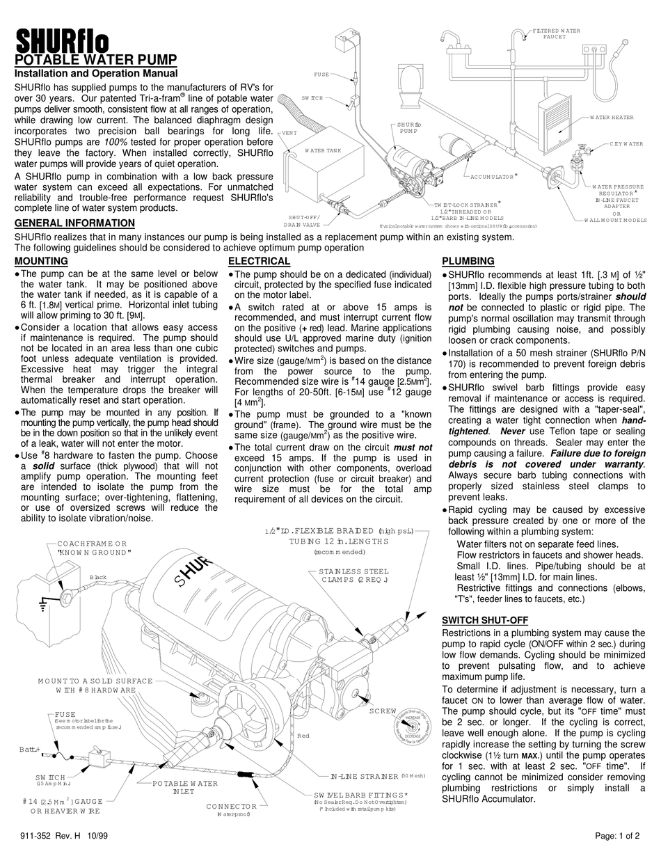
SHURFLO POTABLE WATER PUMP INSTALLATION AND OPERATION MANUAL ...
Checklist for Successful Pump Installation | Pumps & Systems Industry rules of thumb for centrifugal pumps suggest that the foundation size should be three to five times the mass of the pump and driver combined. Base Installation. Install the base on the foundation, and take steps to ensure that the base is flat and level.
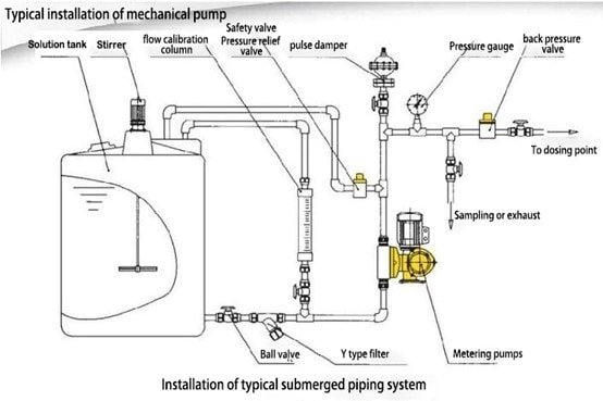
Dosing metering pump working principle - HAOSH Pump
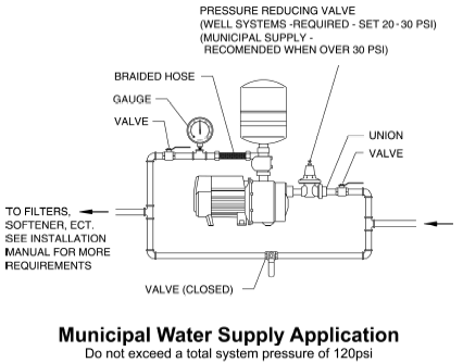
PDF INLINE PRESSURE BOOSTING SYSTEM - Lowe's Decide on a location for the pump installation that is suitable based on the enclosure rating of the Inline Pressure Boosting System. ... The Inline Pressure Boosting System is designed to increase a system's usable pressure whenever water is in use. Shown below is a diagram of the "required" and "recommended" components of a typical ...

How to Install a Davies, Craig Electric Water Pump (EWP) as ...
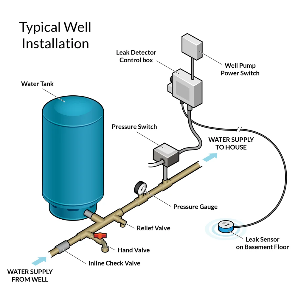
PDF Well Pump & Pressure Tank Diagram - Clean Water Store Installed near the tank inlet to hold water in the tank during pump installation when the pump is idle. 8. Tank Tee Connets water line from pump to pressure tank and service line from tank to house. Taps are provided to accept Pressure Switch, Pressure Gauge, Drain Valve, Relief Valve, Sniffer Valve, etc. 9. Drain Valve Drain easy draining of ...
SEAFLO Washdown Pumps for Boats | 17.0 LPM 12V Quick Connect ...
Water Pump Installation and Fitting at Home/ Water Pump ... Keywards:toilet repairplumbing servicesemergency plumberdrain cleanerlocal plumberswater heater installationplumbing companiesplumbers near meclogged drainbl...

Grundfos UNI-E CM3-5 Variable Speed Water Booster Pump (1.0HP)
How to Install a Well Pump - The Home Depot Install a one-way check valve in the feed line that goes to the pump. This will keep water in the shallow well pump and the plumbing system instead of going back down into the well. Run the shallow well pump and check several water samples before you use them. The water should be clean and free of silt, sand or other materials before you use it.

How to install water pump for domestic or industrial
Water Pump Installation Diagram Needed: Someone Else Took ... Install the water pump with a new gasket. Install a 135.5 mm stud at location No. 5 and tighten to 7 Nm (62 inch lbs.). Install a 137 mm stud at locations No. 4, 6, 7 and 8, and tighten to 7 Nm (62 inch lbs.). Install the water pump with a new gasket. Tighten the nuts and bolts in the sequence shown.
MPP Solar Inc » SP Series (Single Phase, 3-Phase)
Pool Plumbing Diagram & Layout Schematic Examples Be sure to carefully analyze your swimming pool pump and filter installation diagram before creating any permanent seals. Water. Water is the central element that keeps everything in your swimming pool - systems and equipment - in excellent working order. Keep water level well-topped up to protect the spa combination plumbing equipment.

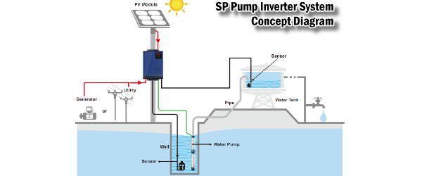
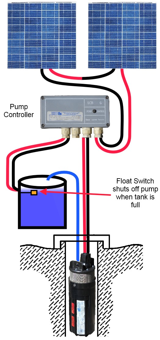
Schematic diagram of a solar water pump. Optional components ...
THE TYPICAL PUMP INSTALLATION SET UP - The Process ... So the complete Typical Pump Installation Setup For A Centrifugal Pump is shown in the below schematic: The flow to this Centrifugal Pump goes from Tank → Suction Gate Valve → Pipe Diameter Reducer → Pump Suction/Pump Discharge → Pipe Diameter Expansion → Check Valve → Discharge Gate Valve → Distribution Header Pipe

WATER PUMP INSTALLATION WORKS!!
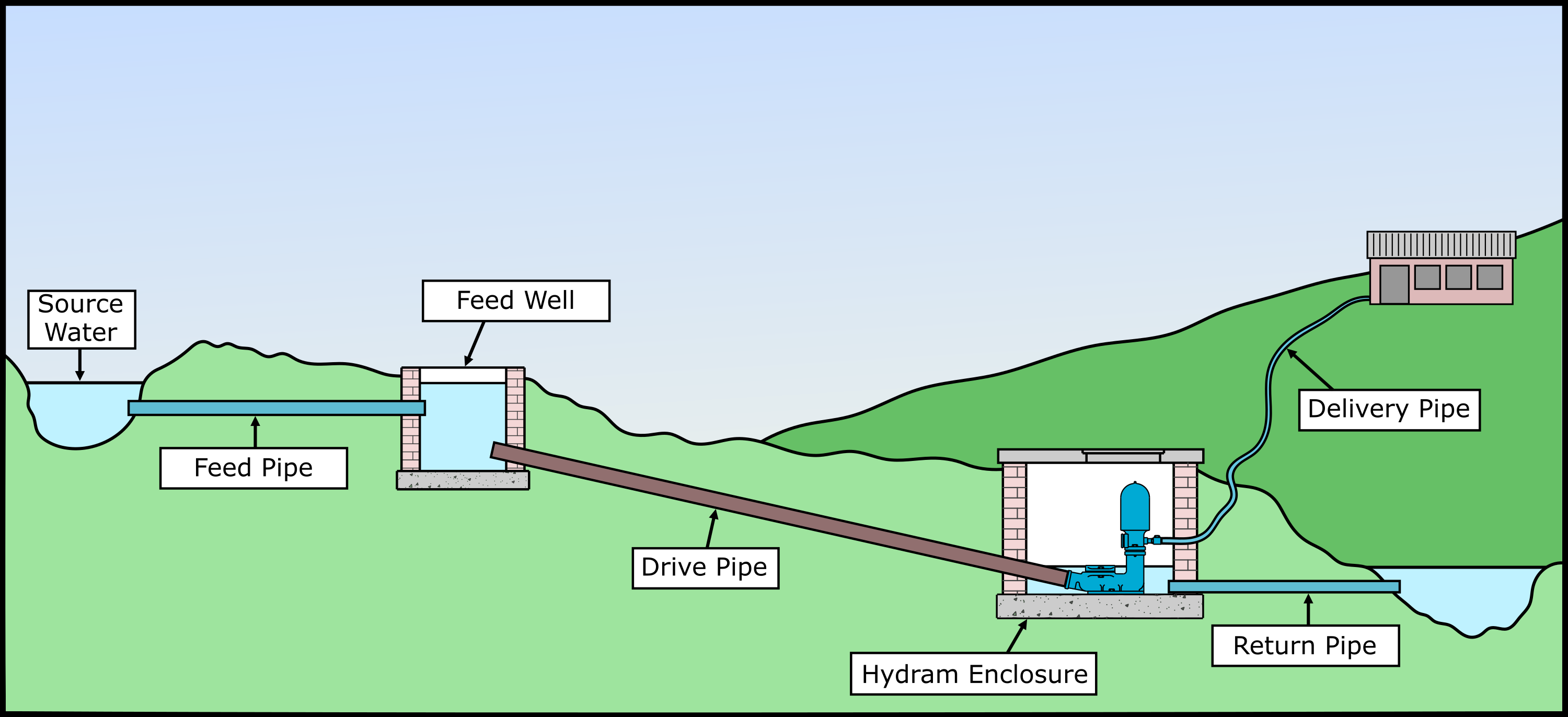
Installation - Blake's Hydram water pump installation

Pump Installation

Water Pump, 12V/24V 120W Diaphragm Water Pump, for High ...

WAVLY Auto Cut, Manual ON, Automatic Off Controller ...

How to wire a microswitch tap and water pump | Off-Grid Camper

Schematic diagram of PV water pumping system. | Download ...

Hand pump - Wikipedia
How to Install Water Pressure Booster Pumps | PumpStoreUSA.com

Rainbank Solutions | Davey Water

Schematic Diagram of the Proposed Water Pumping System ...
How to Use a Submersible Water Pump - 24 Volt Wiring Diagram

float switch wiring diagram for water pump

Electric Pump Auto-Manual Wiring diagrams (3-Phase Motors ...

How To Pick The Best RV Water Pump For Your RV - RVshare.com

float switch wiring diagram for water pump - YouTube ...
Myers QD Series Shallow Well Jet Pumps Buyers Guide & Review

Grundfos SQFlex Solar Water Pump Wiring Diagram

Water Pump, 12V/24V 120W Diaphragm Water Pump, for High ...

Two Line Jet Pumps for Water Wells: Installation & Repair ...
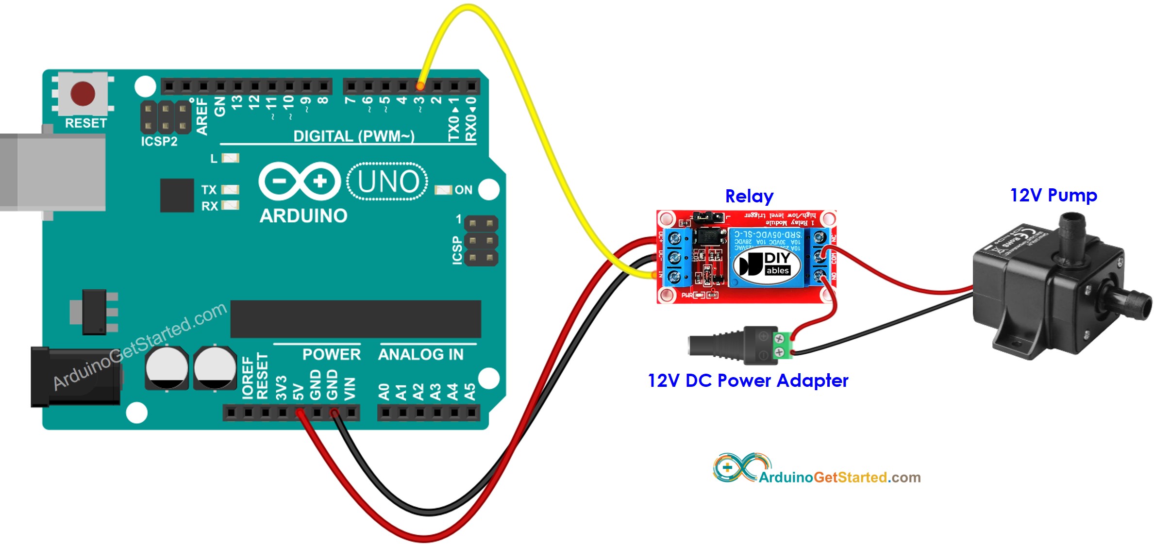
Arduino - Controls Pump | Arduino Tutorial

Vortex Water Pump High Water Pressure Booster Pump For Shower ...

How to Replace a Well Pump (with Pictures) - wikiHow
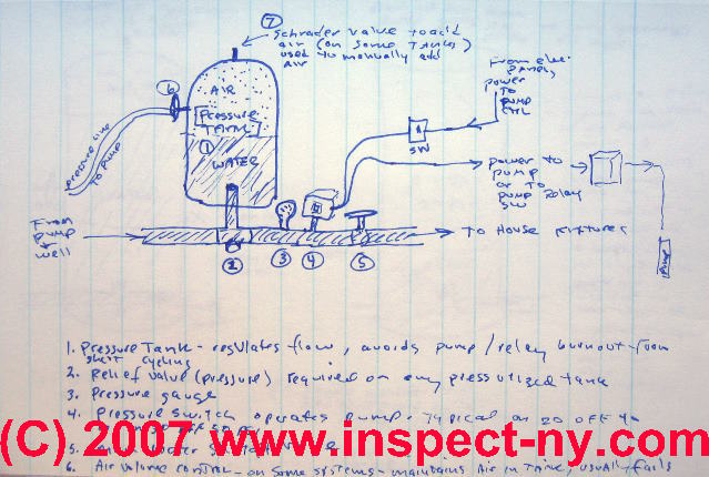
Photo Guide to Well Water Pump Controls & Switches - private ...

SOLAR WATER PUMP WIRING DIAGRAM @... - GRAND Technologies LTD ...
Two Line Jet Pumps for Water Wells: Installation & Repair ...

Water - Pump Installation - Bhudeva
Leak Defender RS Installation Guide — Tec Innovators
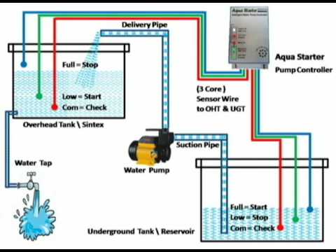
INSTALLATION OF AUTO WATER PUMP CONTROLLER - AQUA STARTER
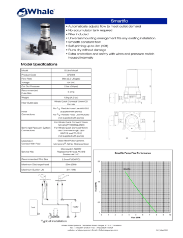
Whale Smartflo water pump instruction manual | Manualzz

Diagram for REVERSE-OSMOSIS-BOOSTER-PUMP - H2O Distributors
0 Response to "45 water pump installation diagram"
Post a Comment