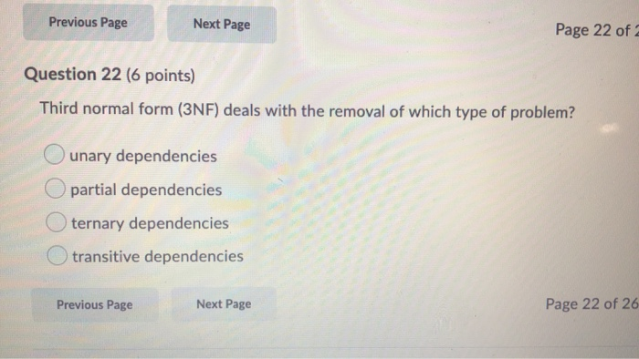
43 in an er diagram, primary keys are indicated by ____.
IT 214 Quizzes Flashcards | Quizlet In an ER diagram, primary keys are indicated by ____. underlining. The Crow's Foot model is less implementation-oriented than the Chen model. False. Some attributes are classified as ____. Correct simple. Relationships operate only in one direction. false. The word "entity" in the ER model corresponds to a table. Module 2 - Ch3&4 Flashcards - Quizlet (T/F) In an ER diagram, primary keys are usually bolded. False (T/F) The Crow's Foot model is less implementation-oriented than the Chen model. False existence-independent entity entity can exist apart from one or more related entities (T/F) Connectivities and cardinalities are established by business rules. True
ER Diagram: Entity Relationship Diagram Model | DBMS Example ER Diagram stands for Entity Relationship Diagram, also known as ERD is a diagram that displays the relationship of entity sets stored in a database. In other words, ER diagrams help to explain the logical structure of databases. ER diagrams are created based on three basic concepts: entities, attributes and relationships.

In an er diagram, primary keys are indicated by ____.
Primary Key In Er Diagram - ERModelExample.com Primary Key In Er Diagram - Entity Relationship is a higher-stage conceptual info model diagram. Entity-Relation model is founded on the notion of real-community organizations and also the relationship between the two. ER modeling allows you to examine info specifications systematically to produce a properly-created database. Logical DB design practice Flashcards | Chegg.com A. The preferred placement for a foreign key when working with a 1:1 relationship is to _____. a. use the same primary key for both entities. b. create a bridge entity. c. place a foreign key in one of the entities. d.. place a foreign key in both entities. C. Composite primary keys are particularly useful as identifiers of composite entities ... What is the symbol for foreign key in ER diagram ... How are keys identified in an ER diagram? The primary key is indicated in the ER model by underlining the attribute. A candidate key is selected by the designer to uniquely identify tuples in a table. It must not be null. A key is chosen by the database designer to be used as an identifying mechanism for the whole entity set.
In an er diagram, primary keys are indicated by ____.. IT Quiz 4 - Subjecto.com In an ER diagram, primary keys are indicated by ____. Underlining. In the ERD, cardinality is indicated using the ____ notation. Min,Max. Knowing the ____ number of entity occurrences is very helpful at the application software level. Maximum and Minimum. Making sure all ____ are identified is a very important part of a database designer's job. CPT 242 Final Flashcards | Chegg.com In an ER diagram, primary keys are indicated by ____. Underlining. In the ERD, cardinality is indicated using the ____ notation. Min,Max. Min,Max. Maximum and Minimum. Making sure all ____ are identified is a very important part of a database designer's job. Business Rules. Chapter 4 Flashcards | Chegg.com A weak entity has a primary key that is partially or totallyderived from the parent entity in the relationship. ... In an ER diagram, primary keys are indicated by ____. a. bolding. c. underlining. b. italics. d. a special font. c. underlining. The ideal number of attributes used to make up a primary key is____. a. zero. c. two. b. one. d. six ... How To Represent A Foreign Key In Er Diagram ... How To Represent A Foreign Key In Er Diagram - Entity Relationship Diagrams are the most effective tools to convey in the complete process. These diagrams are definitely the graphical reflection in the stream of information and information. These diagrams are most frequently used in enterprise agencies to produce information traveling simple.
uml - how to show primary keys which include foreign keys ... The standard way to indicated that an attribute (or set of attributes) is used as the primary key is by underlining them in the ER diagram.. but how do I show that a foreign key is part of a composite primary key if the foreign key isn't show in the ER diagram? I'm using the UML notation for ER diagrams. key uml entity-relationship Share IT Quiz 4 Flashcards | Quizlet In an ER diagram, primary keys are indicated by ____. Underlining. In the ERD, cardinality is indicated using the ____ notation. Min,Max. Knowing the ____ number of entity occurrences is very helpful at the application software level. Maximum and Minimum. DBMS Chapter 4 Review Flashcards - Quizlet In an ER diagram, primary keys are indicated by ____. a. bolding c. underlining b. italics d. a special font. c. underlining. The ideal number of attributes used to make up a primary key is ____. a. zero c. two b. one d. six. b. one. Exam 2 MySQL Flashcards - Quizlet ____ 133. The first step in developing the conceptual model using ER diagrams is to ____. a. normalize the entities b. complete the initial ER diagram c. identify, analyze, and refine the business rules d. define the attributes, primary keys, and foreign keys for each of the entities
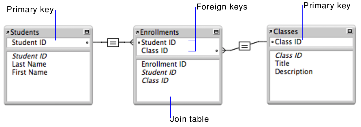
Primary and Foreign Keys - DePaul University There is no standard method for representing primary keys in ER diagrams. For this article, the name of the primary key followed by the notation (PK) is written inside the entity box. An example is shown in below: Validate Keys and Relationships. Basic rules governing the identification and migration of primary keys are: DB Ch. 4 Quiz Questions Flashcards | Chegg.com A strong relationship exists if the primary key of the related entity contains at least one primary key component of the parent entity: true or false True In an ER diagram, primary keys may be indicated by the letters PK and by ___: Underlining, Italics, Bolding, or The Letter Case › pmc › articlesHow Do the Nurses Cope with Job Stress? A Study with Grounded ... Sep 01, 2017 · The diagram of the nurses’ coping process with job stress Due to the stressful nature of the nursing work, facing inappropriate communication in the workplace, stressful work environment, and lack of sufficient competency of self or coworkers in performing some tasks, nurses feel stressed out at their work on a daily basis. Entity-Relationship Diagram Symbols and Notation - Lucidchart ER diagrams help users to model their databases by using various tables that ensure that the database is organized, efficient, and fast. Keys are used to link various tables in a database to each other in the most efficient way possible. Primary Keys
In ER diagram ,is it possible that primary key is not showing ...
› publication › 275208316(PDF) 270 MINI ELECTRONICS PROJECT WITH CIRCUIT DIAGRAM Apr 20, 2015 · circuit diagram help from this book. Give your feedback by mailing me. ... This tim er has a . time duration of up to two hours, which is sufficient for m ost day-to-day activities [8]. 11.

Chapter 4 - Review Questions Pages 1-8 - Flip PDF Download ...
Chapter 8 The Entity Relationship Data Model - BC Open ... The primary key is a candidate key that is selected by the database designer to be used as an identifying mechanism for the whole entity set. It must uniquely identify tuples in a table and not be null. The primary key is indicated in the ER model by underlining the attribute.

Chapter 4 - Review Questions Pages 1-8 - Flip PDF Download ...
How to set up Primary Keys in a Relation? - Stack Overflow I wish to know how to correctly set up Primary Keys in a Relation. E.g. we have ER-diagram which contain elements: There is no ERD to examine. Ok, in the Update you have an example. Perfect for your questions, because it is a set of user views of the data, and the modelling can now begin. But note, that is not an ERD or a Model.

Question 13 2 out of 2 points Contents of the CUSTOMERS table ...
Entity-Relationship modeling - Loyola University Chicago The goal of the E-R modeling process is to create an E-R diagram, which we can then more-or-less mechanically convert to a set of tables. Both entities and relationships will correspond to tables; entity tables will often have a single-attribute primary key while the key for relationship tables will almost always involve multiple attributes.
What is Entity Relationship Diagram (ERD)? - Definition from ...
Erd Composite Key - ERModelExample.com Erd Composite Key -ER is really a high-level conceptual data product diagram.Entity-Relation version is based on the notion of actual-entire world entities as well as the relationship between them. ER modeling allows you to analyze info requirements systematically to produce a properly-designed data base.
ER Diagram: Entity Relationship Diagram Model | DBMS Example
How is a composite entity represented in an ERD and what ... In ER diagram, a composite key is indicated when several attribute names are underlined to specify its participation in the PK. Similarly, what is a composite entity when is it used provide an example? Entities that exist to represent the relationship between two or more other entities are known as composite entities.
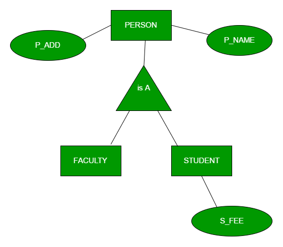
Generalization, Specialization and Aggregation in ER Model ...
dba.stackexchange.com › questions › 76532How to represent foreign key in an ER diagram? Sep 15, 2014 · Sometimes, a relationship will be indicated separately by a diamond. Today, more than half of the ER diagrams floating around are really diagrams of a relational model, and not of an ER model. A relational model has the foreign keys included in the tables, and these serve to implement the relationships which the ER model identifies.

Mapping the ER Model to Relational DBs
What are multivalued attributes and how can they be ... A primary key is a field in a table which uniquely identifies each row/record in a database table. Primary keys must contain unique values. A primary key column cannot have NULL values. A table can have only one primary key, which may consist of single or multiple fields.

Chapter 4 - Entity Relationship (ER) Modeling Compiled By: Mr ...
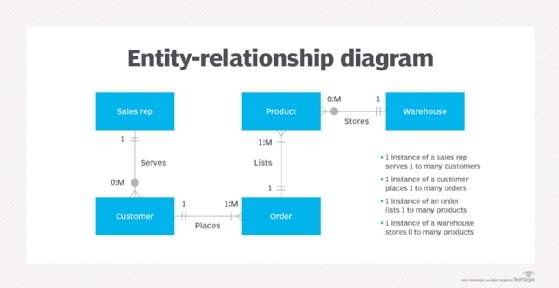
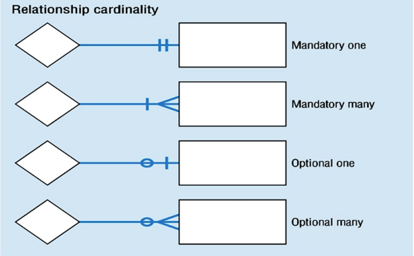
Chapter 2: Entity-Relationship Model The labels "manager" and "worker" are called roles; they specify how employee entities interact via the works-for relationship set. Roles are indicated in E-R diagrams by labeling the lines that connect diamonds to rectangles. Role labels are optional, and are used to clarify semantics of the relationship 5
What is a partial key in database systems? - Quora
database - ER diagram to relational schema - Stack Overflow The primary key of the relation is indicated in the ER diagram. For every relationship set (single-bordered diamond), create a relation that contains the primary keys of associated entity sets, as well as any dependent attributes of the relationship set. The primary key of the relation will be composed of the primary keys of those entity sets ...

database - Should every entity have a primary key? And can we ...
IS 301 Ch 4 Quiz: Entity Relationship Modeling Flashcards ... In an ER diagram, primary keys may be indicated by the letters PK and by ____. underlining italics bolding. underlining. If an entity can exist apart from one or more related entities, it is said to be ____-independent. existence relationship business weak. existence.

MappingERDassignF18solutions.pdf - IS3280 Data Management ...
Entity Relationship Diagram ( ERD ) | Explained ER Model ... The ER model helps the database designers to define the logical structure of the database by defining the primary and foreign key constraints. The ER diagram also includes the attribute ( table column ) names and the symbols that indicate the type of the relationship ( cardinality ) exists between the columns ( one-to-one, one-to-many, many-to ...

Data Modeling and Entity Relationship Diagram (ERD)
In an ER diagram, primary keys are indicated by ... In an ER diagram, primary keys are indicated by . 🎓Answer: underlining Recource 214 practice exam

exam question 1 how to draw Entity Relationship Diagram ...
Solved ERD and SQL Purpose The purpose of this ... - Chegg Design your ER Diagram with all entity names, attribute names, primary and foreign keys, relationships, cardinality and participation indicated. You may add entities or attributes as you see fit. You will need to normalise all of your entities, to resolve any many to many relationships.
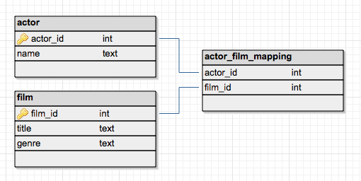
Many-to-many relationships
What is the symbol for foreign key in ER diagram ... How are keys identified in an ER diagram? The primary key is indicated in the ER model by underlining the attribute. A candidate key is selected by the designer to uniquely identify tuples in a table. It must not be null. A key is chosen by the database designer to be used as an identifying mechanism for the whole entity set.
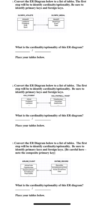
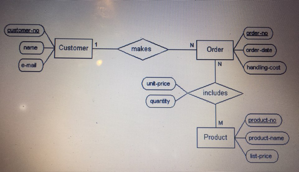
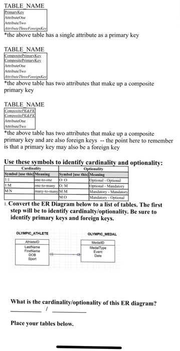
Solved I.Convert the ER Diagram below to a list of tables ...
Logical DB design practice Flashcards | Chegg.com A. The preferred placement for a foreign key when working with a 1:1 relationship is to _____. a. use the same primary key for both entities. b. create a bridge entity. c. place a foreign key in one of the entities. d.. place a foreign key in both entities. C. Composite primary keys are particularly useful as identifiers of composite entities ...

The Entity-Relationship Model
Primary Key In Er Diagram - ERModelExample.com Primary Key In Er Diagram - Entity Relationship is a higher-stage conceptual info model diagram. Entity-Relation model is founded on the notion of real-community organizations and also the relationship between the two. ER modeling allows you to examine info specifications systematically to produce a properly-created database.
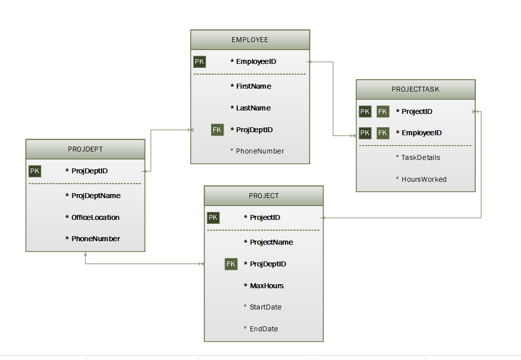
Solved Discuss the topic. In the ER diagram below, identify ...
ER Diagram: Entity Relationship Diagram Model | DBMS Example
Associative entity - Wikipedia

exam question 1 how to draw Entity Relationship Diagram ...
Solved 1. Using Dia, draw the ER diagrams to represent the ...
Solved 3. Identify the entities, attributes, and primary ...

Chapter 4 - Review Questions Pages 1-8 - Flip PDF Download ...
Chapter 8 The Entity Relationship Data Model – Database ...
Solved 4 Convert the ER Diagram below to a list of tables ...

exam question 1 how to draw Entity Relationship Diagram ...

Entity Relationship Diagram (ERD) Tutorial - Part 2 - YouTube

You should always load data from the 1 side of a 1M ...
![Entity Relationship Modeling Examples - Learning MySQL [Book]](https://www.oreilly.com/library/view/learning-mysql/0596008643/httpatomoreillycomsourceoreillyimages234923.png)
Entity Relationship Modeling Examples - Learning MySQL [Book]
![The Entity Relationship Model - Learning MySQL [Book]](https://www.oreilly.com/library/view/learning-mysql/0596008643/httpatomoreillycomsourceoreillyimages234879.png)
The Entity Relationship Model - Learning MySQL [Book]
Chapter 12 Exercises and Answers
Chapter 8 The Entity Relationship Data Model – Database ...
Chapter 4 - Entity Relationship (ER) Modeling Compiled By: Mr ...

Entity-Relationship Modelling - ppt video online download
Chapter 8 The Entity Relationship Data Model – Database ...

Question 8 An is an orderly arrangement used to logically ...
Solved Question 15 (6 points) In an ER diagram, primary keys ...
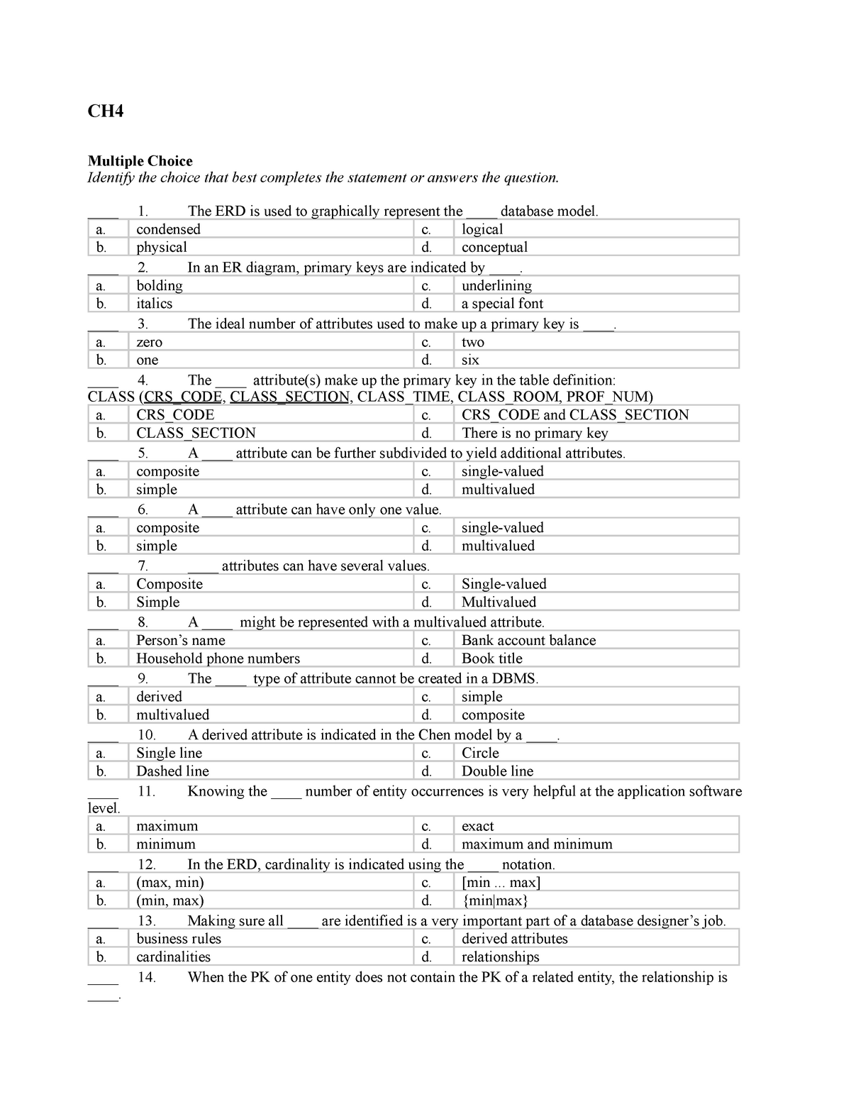
Chapter 4 questions - CH4 Multiple Choice Identify the choice ...
ER Diagram: Entity Relationship Diagram Model | DBMS Example

Primary and Foreign Keys

Creating multiple tables and table relationships

TEST Flashcards | Quizlet
0 Response to "43 in an er diagram, primary keys are indicated by ____."
Post a Comment