44 marine fuel gauge wiring diagram
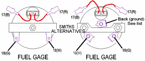
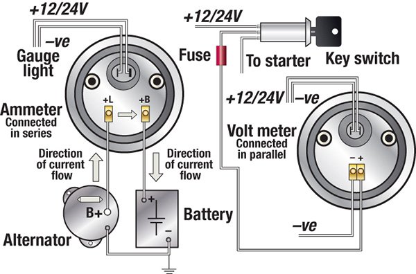
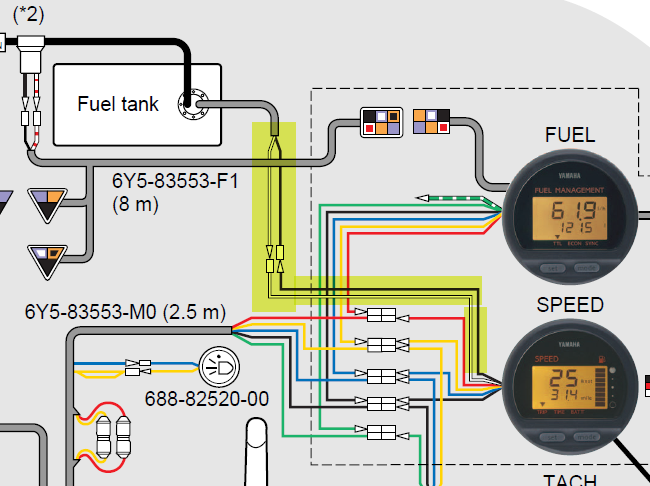
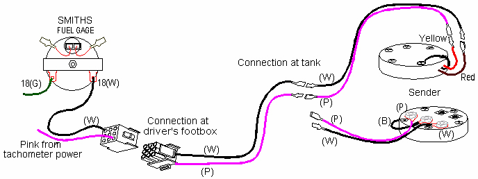
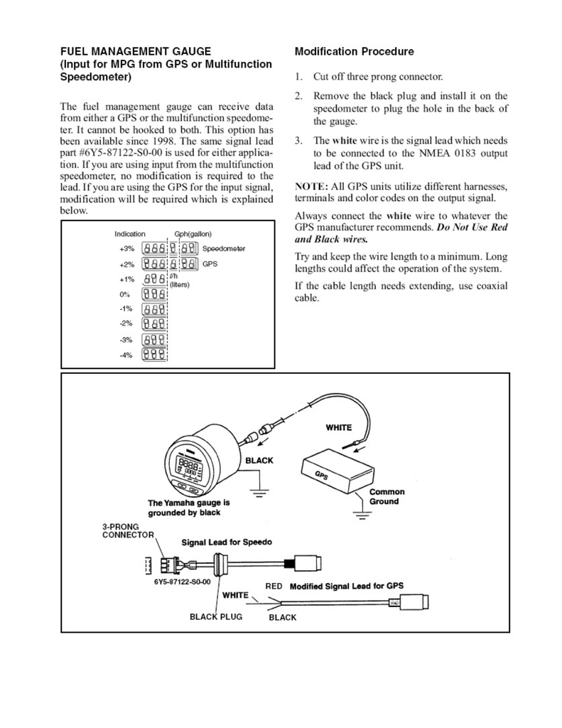
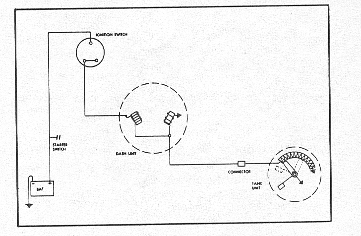
Suzuki Outboard Multifunction Gauge Wiring Diagram - IOT ... New Suzuki Multifunction Gauge Installation Trials The Hull Truth Boating And Fishing Forum. Opt Multi Function Gauge 1 Df175tg E03 Serial Range Four Stroke Outboard 175 Df175 610001 Crowley Marine. Wiring Diagram 300ap The Hull Truth Boating And Fishing Forum. 34000 96l48 Suzuki Outboard Multifunction Smg4 Gauge Display Precision Marine. marine fuel gauge wiring diagram - Wiring Diagram and ... Marine Fuel Gauge Wiring Diagram March 16, 2019 1 0 Fuel gauge and sending unit tech index wiring diagram the hull truth smiths e troubleshooting dual units to one again ribnet forums 1963 1967 corvette engine instrument made easy How To Test And Replace Your Fuel Gauge Sending Unit Sail Magazine
How Do You Wire A Fuel Gauge? - YouTube "How Do You Wire A Fuel Gauge?Watch more videos for more knowledgeFuel Gauge & Sending Unit Troubleshooting - YouTube ...
Marine fuel gauge wiring diagram
Installation Instructions Fuel Gauge - Hodges Marine Cut a 2-1/16" diameter hole in the dash and mount the gauge with the back clamp supplied. For connectorized cases be sure to cut a .175" wide by .115" deep notch to accept the key on the case. See detail on next page. (See diagram on the next page for connections) Standard Case 3. Connect a wire to the gauge stud marked "S" (signal) dual fuel tank wiring diagram/ help - Performance Boats Forum Here is a diagram of what we have. We weeded out alot of useless crap and came up with this. We can switch between senders, but even with the tanks 1/4 full we always get a full reading on the gauge for both tanks and an empty reading in the neutral position. My guess is im switching over a full 12v to the gauge which is giving me this outcome.. Boat Fuel Gauge Not Working? How To Troubleshoot & Fix It ... The fuel sender located inside the fuel tank; The power wire to the gauge; The ground; The sending wire that runs from the sender to the gauge; Boat Fuel Gauge Stuck On Empty or Stuck On Full? To be honest, these boat fuel gauges are pretty simple. They connect to only three wires that run to the gauge. These wires consist of the "power" or ...
Marine fuel gauge wiring diagram. Boat Fuel Gauge Not Working | Boating Mag Here is a quick method of determining whether the fault lies in your boat's fuel gauge or in the fuel gauge sending unit on the tank. You may need a partner to complete this simple task, depending upon how you proceed. Step 1: Locate the boat fuel sending unit. This is often accessed through a deck plate placed over the aft end of the tank. Wiring Diagram Boat Fuel Gauge - Wiring Diagram Line Wiring Schematic For Fuel Gauge On Nonsuch 30 Cruisers Sailing Forums 2 12v Fuel Level Gauge Resistance 240 33 Ohm 24v Rv Universal Oil Meter E 1 F Indicating Range Lighting Background Anti Fogging Rust Waterproof Stainless Stress Frame For Boat Marine Online In Turkey Fxr Fuel Gauge V Twin Forum VDO Documentation - VDO Marine Gauges Standard Resistive Gauges 52mm 12/24 Volt (2011) Standard Resistive Gauges 52mm 12/24 Volt Retrofit Kit (Temperature, Pressure, Level, Trim) (2013) Temperature Resistance Chart (2004) VDO Cylinder Head Temperature Gauge Handlebar/Fairing Mount - 2009. VDO Resitive Gauge wiring Instructions - 2009. Veratron Flex Gauge 52mm NMEA2000 12/24v. Boat Fuel Tank Gauge Wiring Diagram | autocardesign Boat Fuel Tank Gauge Wiring Diagram - wiring diagram is a simplified standard pictorial representation of an electrical circuit. It shows the components of the circuit as simplified shapes, and the power and signal links surrounded by the devices. A wiring diagram usually gives information very nearly the relative incline and deal of devices ...
How to Wire a Marine Fuel Tank Gauge | Gone Outdoors ... Daisy-chain the "-" wire to the ground wire--which may be also be marked "-" or "GND"--of the instrument next to the fuel gauge. Pull the wire from the fuel sender up through your boat's dash. Slip the female blade connector on the wire from the fuel sender onto the "S" terminal of the fuel tank gauge. PDF Gauge and Sending Unit Wiring Diagram and ... - Moeller Marine Recommended Marine Wiring Color Code Direct Current Systems - Under 50 Volts (No diagram required if wiring is in compliance with Tables I and Il) Color Yellow w/Red Stripe (YR) Yellow (Y) Dark Gray (Gy) Brown (Br) Orange (O) ... Fuel Gauge Sender to Gauge IGNTION SWITCH BLACK BULB SENDER GRND SENDER BATTERY GROUND FUEL . Moeller Fuel Gauge Wiring Diagram Moeller Gauge-Wiring Diagram 4″″ Universal Electric Fuel Sender Instructions Electric Fuel . Gauge pointer should be at the position shown in the lower portion of the diagram. To test senders, the resistance values are shown at minimum and full gauge scales. Fuel Systems (Marine) Voltage - "I" to "G" terminal - 10 to 16 volts. 52 results How To Wire A Boat | Beginners Guide With Diagrams | New ... 5. Install Terminal Block as Breakout Point. If you get your boat's switch panel fully wired ( more on that here ), then you'll have an easy to install wiring harness coming off pre-installed with heat shrink labels, and ring terminals. This is meant to land on a terminal block like this one.
Faria Fuel Gauge Wiring - Wiring Diagram Pictures REPAIR On the Fuel Level Sender measure down from the bottom of the wire of the gauge.Boat fuel gauges can be troublesome. Here is a quick method of determining whether the fault lies in your boat's fuel gauge or in the fuel gauge sending unit on the tank. You may need a partner to complete this simple task, depending upon how you proceed. Wiring Diagram For A Boat Fuel Gauge - Wiring Diagram Line Wiring Schematic For Fuel Gauge On Nonsuch 30 Cruisers Sailing Forums Installation Troubleshooting Boat Gauges Instrumenteters Boatus 2 12v Fuel Level Gauge Resistance 240 33 Ohm 24v Rv Universal Oil Meter E 1 F Indicating Range Lighting Background Anti Fogging Rust Waterproof Stainless Stress Frame For Boat Marine Online In Turkey Faria Fuel Gauge Wiring - Wiring Diagrams Connect a wire to the gauge stud marked "S" (signal) and secure with nut and lock washer. contact Faria® Marine Instruments Customer Service between AM and PM These instructions concern only fuel gauge installations.Teleflex Fuel Gauge Wiring Diagram | Wiring LibraryFaria Beede Instruments, Inc. Fuel gauge wiring diagram request | Boating Forum - iboats ... Re: Fuel gauge wiring diagram request There are four connections on the gauge itself. 1) +12V when the key is on. That connection can come from the +12V connection on any other gauge as they are simply daisy chained from one to the next. 2) Ground. Same thing -- gauges are grounded by daisy chaining them together. 3) Light -- same thing.
Engine Instrument Wiring Made Easy - Boats.com Beginning with the tachometer, Fig. 1 here shows the back of a typical gauge. At the top left of the diagram, we see the cylinder selector switch. Most vendors will use one tachometer head to cover a variety of engines. Make sure this switch is set to the number of cylinders for your engine.
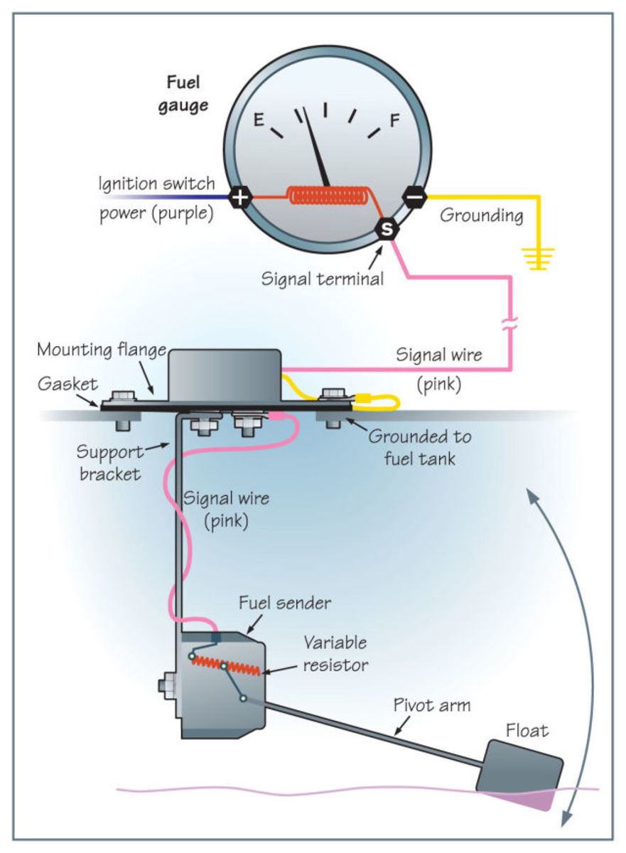
How to Test and Replace your Fuel Gauge ... - Sail Magazine Fuel Gauge Check the wiring diagram that comes with the kit and mark the back of the new fuel gauge with symbols for each post: "S" for the sender, "G" or "—" for the ground, and "I" for the ignition. Install the new gauge, reconnect the wiring and turn on the power. The fuel gauge should now show the correct fuel level in the tank.
Honda Outboard Gauge Wiring Diagram - IOT Wiring Diagram Honda Outboard Gauge Wiring Diagram. By IOT | August 26, 2021. 0 Comment. Honda marine bf135 wiring diagram pdf manualslib outboard engine tacklereviewer typical instrument to motor cable harness cruisers sailing photo gallery made easy boats com what protocol for pair of digital 2008 bf 150 hp s warning buzzer mystery calling all experts the ...
Teleflex Fuel Gauge Wiring Diagram - schematron.org Remove the gauge's sender wire. Turn on the power. The pointer of whatever gauge you are checking should be at the position shown in the upper portion of the diagram at right. 2. Next, take a short wire and connect to sender ter mi nal and ground terminal (shorting sender terminal to ground). Gauge pointer should be at the position.
E26 Fuel Gauge Sender and Ground | EY.o Information Exchange Here are the Aoditeck sender install instructions : -Connect ground (blue) wire from AODITECK sending unit to a common grounding hook-up. -Connect signal (brown) wire from AODITECK sending unit to gauge hook-up. If your gauge has color coded hook-ups, maintain this coding as you connect the sender and ground wires. Last edited: Jun 10, 2021.
Wiring Schematics - Marine Power USA Wiring Schematics Distributor Kit Wiring Diagram J1939 to NEMA2000 Wiring MEFI 4 MEFI 4 Engine Controls Schematic 4.3L - 5.7L MEFI 4 ECM Circuit Board Layout (5.7-6.0-8.1L) MEFI 4 Engine Controls Schematic 6.0L MEFI 4 ECM Engine Wiring Diagram 8.1L 5.7L Wiring Harness Schematic (472605) MEFI 5 MEFI 5 Engine Controls Schematic 6.0L MEFI 5...
Troubleshoot Your Boat's Fuel Gauge | Boating Mag The gauge has three connections: ground (black), sender (pink), and 12-volt DC positive. The positive wire can be red, if wired to an accessory switch, or purple, if wired to the key switch. Also, the back of the gauge will show which terminal is which with embossed markings (S for sender, G for ground, etc.). Troubleshooting Your Gauge
Marine How To - DIY for Boaters - Marine How To Marine How To is the go-to site for DIY boat owners to find in depth, step-by-step articles for maintenance, upgrades and to find brutally honest insight from marine industry professionals. Marine How To is 100% reader supported with no advertisers or sponsors to appease. You can support us, and help keep the content free, by shopping our WEB ...
Boat Fuel Gauge Not Working? How To Troubleshoot & Fix It ... The fuel sender located inside the fuel tank; The power wire to the gauge; The ground; The sending wire that runs from the sender to the gauge; Boat Fuel Gauge Stuck On Empty or Stuck On Full? To be honest, these boat fuel gauges are pretty simple. They connect to only three wires that run to the gauge. These wires consist of the "power" or ...
dual fuel tank wiring diagram/ help - Performance Boats Forum Here is a diagram of what we have. We weeded out alot of useless crap and came up with this. We can switch between senders, but even with the tanks 1/4 full we always get a full reading on the gauge for both tanks and an empty reading in the neutral position. My guess is im switching over a full 12v to the gauge which is giving me this outcome..
Installation Instructions Fuel Gauge - Hodges Marine Cut a 2-1/16" diameter hole in the dash and mount the gauge with the back clamp supplied. For connectorized cases be sure to cut a .175" wide by .115" deep notch to accept the key on the case. See detail on next page. (See diagram on the next page for connections) Standard Case 3. Connect a wire to the gauge stud marked "S" (signal)















0 Response to "44 marine fuel gauge wiring diagram"
Post a Comment