45 free body diagram torque
Axial Force Diagrams and Torque Diagrams. As an alternative to splitting a body in half and performing an equilibrium analysis to find the internal forces ... • Draw free-body diagram and label. • Choose axis of rotation at point where least information is given. • Extend line of action for forces, find moment arms, and sum torques about chosen axis: • Sum forces and set to zero: F. x = 0; F. y = 0
t= F r sin q F=ma for rotation: t=Ia. Work done by torque W = t q Use F=ma, t=Iato solve for a, a, tension, time. Use conservation of energy to solve for speed. Equilibrium SF = 0 S t= 0 » Can choose any axis or pivot around which to compute torques. Trick of the trade: If there is a force on the pivot, the torque it produces is 0!
Free body diagram torque
This is something of a tricky problem, because you have to draw the free-body diagram of the entire ladder to figure out the normal forces, and then draw the free-body diagram of one half of the ladder to complete the solution. This is also what makes it a good example to look at, however. Consider first the free-body diagram of the entire ladder. What is the equation for the torque on the turntable in Figure 8.6. Be sure to label all forces! turntable figure at the top of page 8-10. in terms of constants ... Basic static equilibrium examples that emphasize drawing the free body diagram, choosing an axis, and evaluating torque without bothering to work out the num...
Free body diagram torque. Draw a free-body diagram of the shaft on either side of the cut Use a static-equilibrium equation and the following sign convention to obtain the internal torque at the section Sign Convention Using the right-hand rule, the torque and angle of twist will be positive, provided the thumb is directed outward from the shaft when the Must draw a free body diagram for each, labelled diagrams and all units included. All working out must be shown. ... Question 2 The hollow steel shaft has a diameter of 65 mm and thickness of 5mm, is subjected to a torque and moment produced by a 3 kN force which is 15 mm from the centre of the shafts cross section. The shafts have the same centroid. a. Using Mohr's circle, determine the ... A free body diagram consists of a diagrammatic representation of a single body or a subsystem of bodies isolated from its surroundings showing all the ... Free Body Diagrams for Torque situations usually include a weight for the object experiencing the torque, various or a single support force, and any other ...
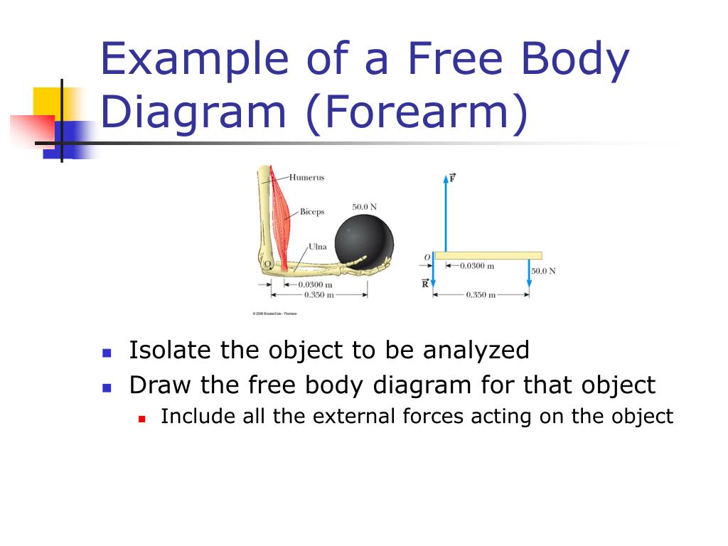
Figure 5.32 (a) The free-body diagram for isolated object A. (b) The free-body diagram for isolated object B. Comparing the two drawings, we see that friction acts in the opposite direction in the two figures. Because object A experiences a force that tends to pull it to the right, friction must act to the left. Because object B experiences a component of its weight that pulls it to the left ... 01.11.2021 · Knowing that portion CD of the brass rod is hollow and has an inner diameter of 60 mm 40 mm, TB = 1600 N·m 36 m mm D a.) Draw an appropriate free body diagram and use it to determine an internal torque between TA = 800 N·m 250 mm 1.) Segment AB, i.e., TAB 375 mm A 400 mm Fig. 2 Free body diagrams • A free body diagram shows a body isolated from other bodies • All external forces and torques acting on it are shown To solve for a body in equilibrium: 1. Decide on the body of interest 2. Draw a diagram of the body isolated from other bodies in contact with it 3. Show all forces and torques acting on the body In this video, we solve a torque diagram without having to use equations. By simply looking at the external loadings, we can easily draw the internal torque...
The diagram shows the position vector from the origin to a particle ... Coordinate-free description. At any instant , the angular ... in the rigid body is located at point P and the vector position of this particle is R i in the lab frame, and at position r i in the body frame. It is seen that the position of the particle can be written: = + The defining characteristic of a rigid body is that ... Figure 5.32 (a) The free-body diagram for isolated object A. (b) The free-body diagram for isolated object B. Comparing the two drawings, we see that friction acts in the opposite direction in the two figures. Because object A experiences a force that tends to pull it to the right, friction must act to the left. Because object B experiences a component of its weight that pulls it to the left ... Each interactive concept-builder presents learners with carefully crafted questions that target various aspects of a discrete concept. There are typically multiple levels of difficulty and an effort to track learner progress at each level. Question-specific help is provided for the struggling learner; such help consists of short explanations of how to approach the situation. Draw a free-body diagram. Show the torque reactions at supports A and C in the correct direction for resisting the applied torque, T. From your free-body diagram, write the equilibrium equation for the torques. Express the torsional equation of equilibrium for the shaft in terms of TA, and TC. B) Write the equation for deformation compatibility ...
Planar rigid body dynamics. If a system of particles moves parallel to a fixed plane, the system is said to be constrained to planar movement. In this case, Newton's laws (kinetics) for a rigid system of N particles, P i, i=1,...,N, simplify because there is no movement in the k direction. Determine the resultant force and torque at a reference point R, to obtain
Torque and Angular Momentum of a Particle The figure below shows a fixed coordinate system OXY Z containing a mass m moving with velocity v, having momentum p , and being acted upon by a resultant force, f . X Y Z O ... The free body diagram depicting the torques on the body is shown below. Note the directions of the unit
Download scientific diagram | Free body diagram for the calculation of the joint force and torque of the upper trunk seg- ment. from publication: Kinetic ...
Why Do Athletic Runners Lean Forward Newtonian Mechanics Forces Acceleration Free Body Diagram Quora
LEXUS Car Manuals PDF & Wiring Diagrams above the page - CT, ES, GS, LS, LX, NX, RC, RX, IS, UX; Lexus Cars EWDs; LEXUS Fault Codes DTC.. Lexus is a division of Toyota, a Japanese company that was created to develop and manufacture luxury cars.. Initially, the models of this brand were designed for sale in the United States, but its popularity has allowed to expand the market in other directions.
11 1 Rotation Torque Begin Rotational Dynamics Read Ch 9 Sec 1 3 Suggested Problems From Ch 7 22 35 36 37 53 55 Hw 11 1 Hw Handout Extended Ppt Download
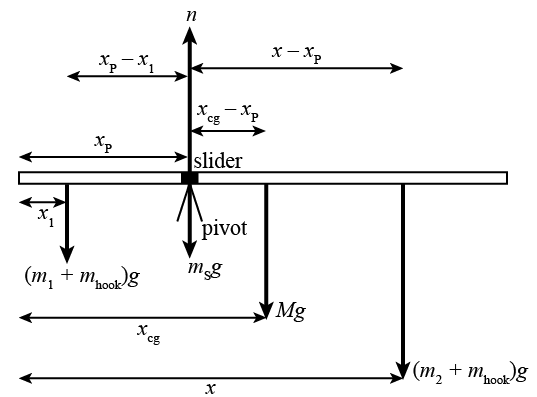
3 Jun 2021 — Torque Diagrams. To investigate situations in static equilibrium more thoroughly, you can make use of an extended free-body diagram that shows ...
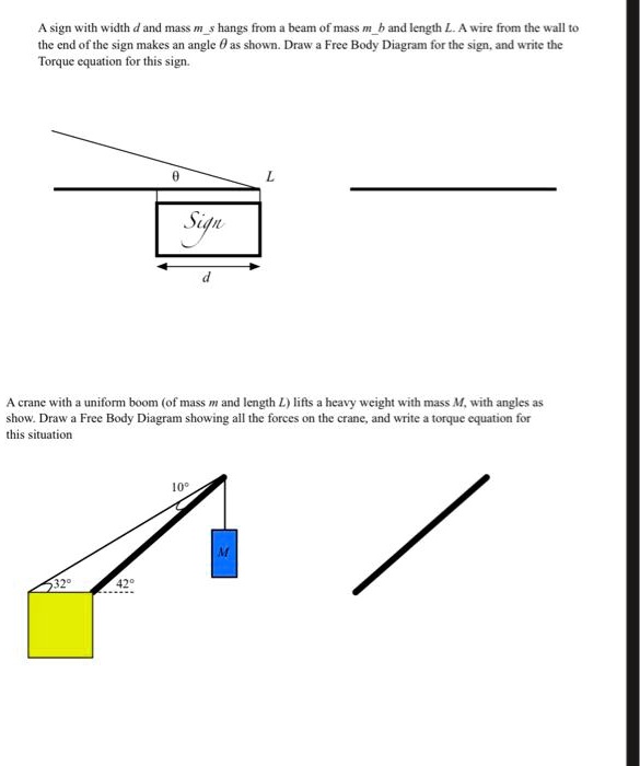
Part D: Drawing and Interpreting Free-Body Diagrams 37. Construct free-body diagrams for the following physical situations at the instant in time for which they are described. As is always done in free-body diagrams, label the forces according to type and draw the arrows such that their length reflects the magnitude of the force.
upward force by pivot. • rod is still subject to the same forces. • no change to free body diagram. • it will rotate, but free body diagram misses this!152 pages
FREE CATALOG; CUSTOMER SERVICE; Wishlist; My Account; Cart 0-$0.00; Shop Kaiser Willys. Search: Search. SHOP . Home / Shop By Diagram / 55-75 CJ-5 Diagrams; 55-75 CJ-5 Diagrams . ESI processing not enabled. Axle Diagrams - Willys CJ-5, 6. Body Diagrams - Willys CJ-5, 6. Brake Diagrams - Willys CJ-5, 6. Clutch Diagrams - Willys CJ-5, 6. Cooling Diagrams - Willys CJ-5. Driveshaft …
Basic static equilibrium examples that emphasize drawing the free body diagram, choosing an axis, and evaluating torque without bothering to work out the num...
What is the equation for the torque on the turntable in Figure 8.6. Be sure to label all forces! turntable figure at the top of page 8-10. in terms of constants ...
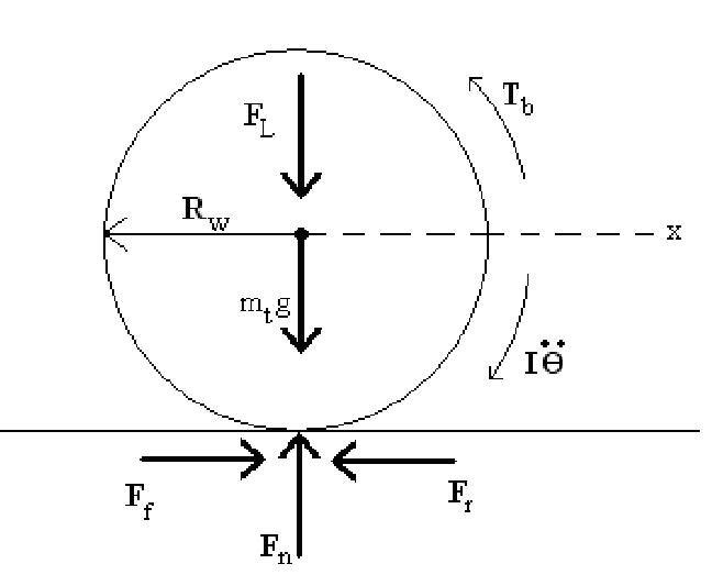
In A Free Body Diagram Should Surface Friction Traction Go In The Opposite Direction To Wheel Torque Quora
This is something of a tricky problem, because you have to draw the free-body diagram of the entire ladder to figure out the normal forces, and then draw the free-body diagram of one half of the ladder to complete the solution. This is also what makes it a good example to look at, however. Consider first the free-body diagram of the entire ladder.
Solved Body Incomplete Fbd 1 Bell Crank Supporting Mass M With Pin Support At A Control Lever Applying Torque To Shaft At 0 Boom 0a Of Negligib Course Hero

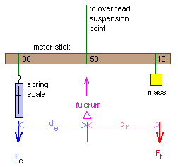
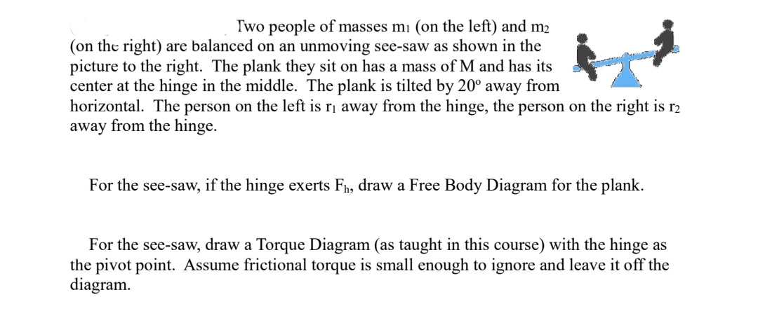
The Easiest Lever To Analyze Is The First Class Lever Seesaw That Is Balanced By Itself The Center Of Gravity Of The Lever Is On The Fulcrum Cg Ppt Download











0 Response to "45 free body diagram torque"
Post a Comment