43 tanabe-sugano diagram
田辺・菅野ダイアグラム(たなべ・すがのダイアグラム、Tanabe-Sugano diagram)は、第4周期dブロック元素の正八面体型錯体における結晶場あるいは配位子場の強さと各スペクトル項のエネルギーの相関を表したグラフのことである。. 1954年に田辺行人と菅野暁によって提唱された。 In coordination chemistry, a ligand is an ion or molecule (functional group) that binds to a central atom to form a coordination complex.The bonding with the metal generally involves formal donation of one or more of the ligand's electron pairs often through Lewis Bases. The nature of metal–ligand bonding can range from covalent to ionic. ...
Print the appropriate Tanabe-Sugano diagram and locate where the ratio of the second to first peak matches that found experimentally. Tabulate the values of v1 / B, v2 / B, v3 / B from the Y-intercepts and Δ/B from the X-intercept. A laboratory experiment based on this is described in more detail in the CHEM2110 lab manual.

Tanabe-sugano diagram
The Orgel and Tanabe-Sugano diagram for d8-configuration can be used to estimate the value of crystal field splitting energy for these transition metal complexes. (a) (b) Figure 39. The (a) Orgel and (b) Tanabe-Sugano diagrams for d8 complexes in the octahedral crystal field. Consider the example of [Ni(H2O)6]2+. 1. This is normally done through a Tanabe-Sugano diagram where energy is plotted against the magnitude of the crystal field splitting parameter for a d3 ion (Figure 2). Figure 2. Tanabe-Sugano Diagram appropriate for Cr(III). The vertical arrow denotes the relevant d-d transition for determining ∆o. After Tanabe, Y.; Sugano, S. J. Phys. Soc. Jpn. 1954, 9, 753 . Chem242. Int. Inorg. Chem. UMass ... The baseline in the Tanabe-Sugano diagram represents the lowest energy or ground term state. The d 2 case (not many examples documented). The electronic spectrum of the V 3+ ion, where V(III) is doped into alumina (Al 2 O 3), shows three major peaks with frequencies of: ν1=17400 cm-1, ν2=25400 cm-1 and ν3=34500 cm-1.
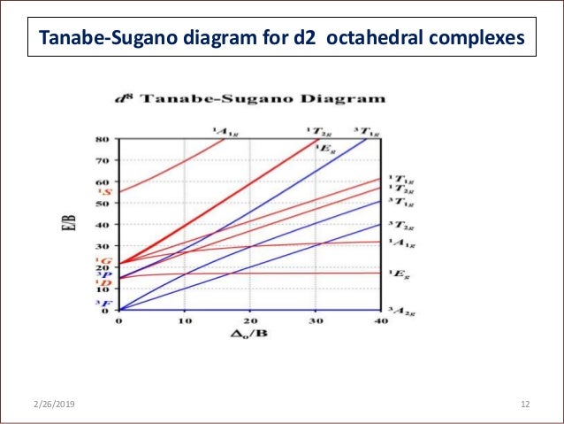
Tanabe-sugano diagram. Tanabe-Sugano Diagrams and Charge Transfer Chapter 11 extra material (to finish Chapter 11) Symmetry Labels for Configurations Free ion termssplit into statesin the ligand field, according to symmetry: ... a d7complex so we can use the d7 Tanabe-Sugano diagram from the last slide. 9.12: Tanabe-Sugano Diagrams. Tanabe-Sugano diagrams are used in coordination chemistry to predict electromagnetic absorptions of metal coordination compounds of tetrahedral and octahedral complexes. The analysis derived from the diagrams can also be compared to experimental spectroscopic data. Armed with spectroscopic data, an approximation to ... TanabeSugano. A python-based Eigensolver for Tanabe-Sugano- & Energy-Correlation-Diagrams based on the original three proposed studies of Yukito Tanabe and Satoru Sugano for d 2-d 8 transition metal ions:. On the Absorption Spectra of Complex Ions. Tanabe-Sugano diagram for d2 octahedral complexes 2/26/2019 12 13. Advantages over Orgel diagrams • Tanabe-Sugano diagrams can be used for both high spin and low spin complexes, unlike Orgel diagrams which apply only to high spin complexes. • In a Tanabe-Sugano diagram, the ground state is used as a constant reference, in contrast to ...
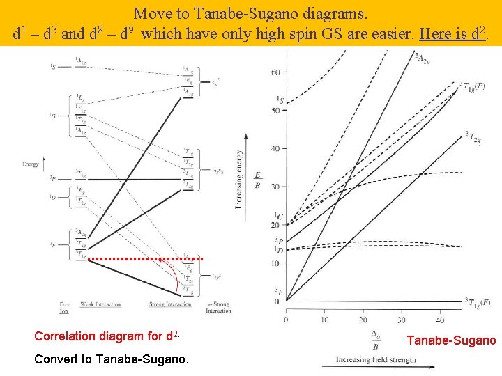
d2Tanabe-Sugano Diagram E / B ∆o/ B 3F 3P 3T 1g (3P) 3A 1g 3T 2g (3F) 3T 1g ~15B ~∆o ~∆o E1 E2 E3 E is the energy of the excited state relative to the ground state B is the Racah parameter for e--e-repulsion The example on page 427 of your text shows how to use this chart to fit the experimental data (E1, E2, and E3) for [V(OH2)6]3+to ... A step-by-step tutorial on assigning the transitions in the UV-vis spectrum of a d7 system using a Tanabe-Sugano Diagram. Lecture 4 May 11: Tanabe Sugano Diagrams A Tanabe-Sugano (TS) diagram plots the energy dependence of the various ligand field states (or terms) with field strength. The strength of the ligand field is defined by Dq, which is related to the octahedral crystal field splitting by 10Dq = ∆o. The energy of the state is given by E. Tanabe-Sugano diagrams are used in coordination chemistry to predict absorptions in the UV, visible and IR electromagnetic spectrum of coordination compounds. The results from a Tanabe-Sugano diagram analysis of a metal complex can also be compared to experimental spectroscopic data. They are qualitatively useful and can be used to ...
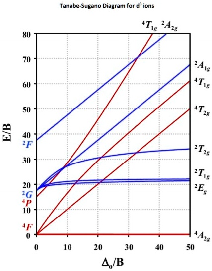
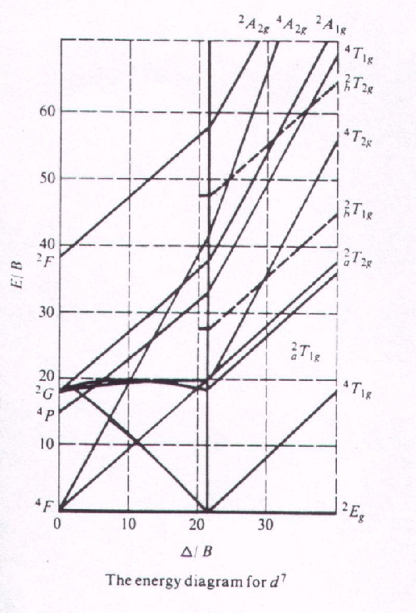
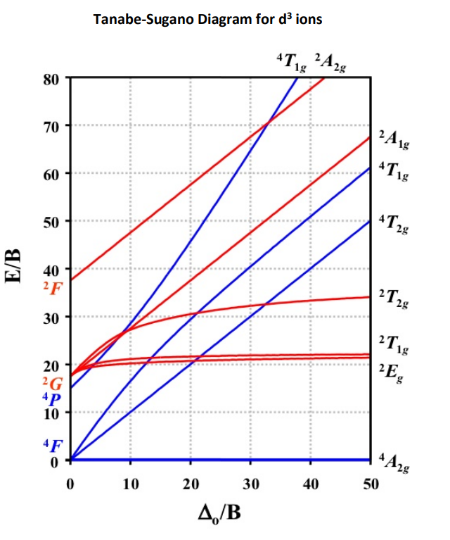
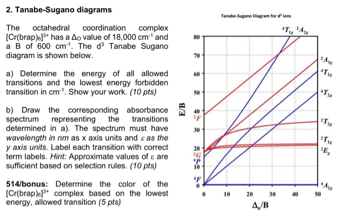
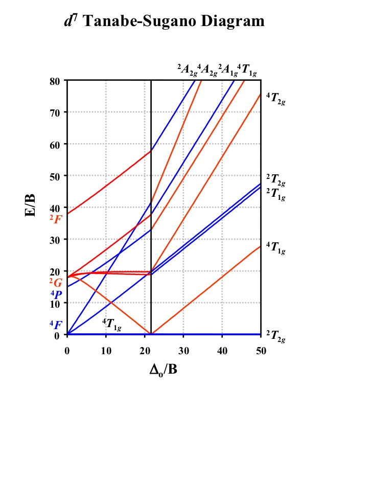
Tanabe-Sugano diagram for d3 octahedral complexes. TS d3 diagram. Interpolation of the graph to find the Y-axis values for the spin-allowed transitions gives. The different free ion terms for an electron configuration have different energies due to variations in electron-electron repulsion. The different.Procedure for a Cr (III) system using ... 2. The Tanabe Sugano diagram of the complex along with the absorption spectrum is shown below (figure 5). Figure 5: Tanabe-Sugano diagram and absorption spectrum for complexes with d7 configuration In this case the free ion term of ground state is 4F which splits into three states of same spin multiplicity namely 4T 1g, 4T 2g and 4A 2g. The ... Tanabe-Sugano Diagrams. Tanabe-Sugano diagrams are used in coordination chemistry to predict electromagnetic absorptions of metal coordination compounds of tetrahedral and octahedral complexes. The analysis derived from the diagrams can also be compared to experimental spectroscopic data. Armed with spectroscopic data, an approximation to the ... Tanabe-Sugano diagram에서 실제로, B 값을 구할 수 있는데요. 이 값이 크면 그만큼 불안정하다는 것이고, 작으면 안정하다는 것으로 해석하시면 됩니다. 그리고, 책 혹은 Tanabe-Sugano diagram에서 Nephelauxetic Effect 네팔로제릭 효과라는 게 등장하는데요.
30.11.2021 · Ground state vs excited state worksheet answers. V (i. atoms of a gas or a vapor are excited, for example by heating or by applying an electric field, their electrons are able to pass from their ground state to more elevated levels of energy

Tanabe-Sugano (TS) energy-level diagram specific for the metal-complex geometry under study. Despite this requirement, many formally and informally published experiments ignore the use of TS diagrams in the quantitative determination of ∆0 or provide the reduced data on relatively simple systems and leave it as an academic process to ...

Tanabe-Sugano diagrams can also be used to predict the size of the ligand field necessary to cause high-spin to low-spin transitions. In a Tanabe-Sugano diagram, the ground state is used as a constant reference. The energy of the ground state is taken to be zero for all field strengths, and the energies of all other terms and their components are plotted with respect to the ground term. The x ...

Orgel and Tanabe-Sugano Diagrams for Transition Metal Complexes (d1 – d9 States) It is a well-known fact that electronic transitions are always accompanied by vibrational as well as rotational changes which results in a considerable broadening of the bands in the UV-visible spectra of transition metal complexes too. The nature of these ...

A series of JAVA applets of Tanbe-Sugano diagrams were developed by Prof. Robert Lancashire at the University of the West Indies. These diagrams allow students to determine delta o /B values based on ratios of peak energies without the pain of rulers and drawing lines. There are also features that allow a person to input values and automatically calculate certain parameters.
TANABE-SUGANO DIAGRAMS. Tanabe-Sugano diagrams show both low-spin and high-spin cases, and also show spin-forbidden transitions. They even show terms that are near to, but not the ground state! Also, as previously mentioned, there is a hole formalism that says that a dn diagram for octahedral complexes applies to d10−n tetrahedral complexes.

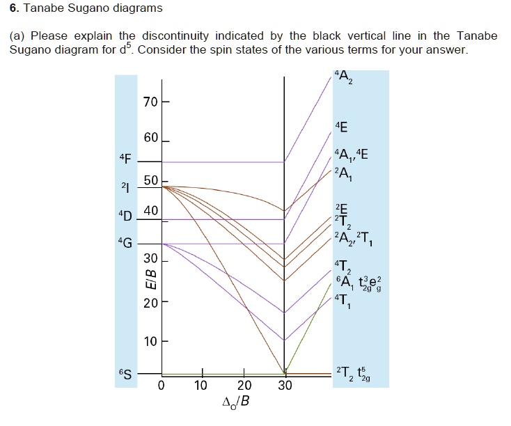
Tanabe Sugano Exercises These questions deal in part with concepts presented in today's lecture and assigned readings. Have a look at the Tanabe-Sugano diagram for the d 5 case. What is the term symbol for the ground state of a free d 5 ion (where Δ o /B = 0)?; What is the term symbol for the ground state of a d 5 ion satisfying the condition that Δ o /B = 20?; What is the physical meaning ...
The x-axis of a Tanabe–Sugano diagram is expressed in terms of the ligand field splitting parameter, Dq, or Δ, divided by the Racah parameter B. The y-axis is in terms of energy, E, also scaled by B. Three Racah parameters exist, A, B, and C, which describe various aspects of interelectronic repulsion. A is an average total interelectron repulsion. B and C correspond with individual d ...
Download scientific diagram | Tanabe-Sugano energy-level diagram of Mn 4+ in the YAG host. from publication: Enhanced Luminescence of Mn4+: Y3Al5O12 Red Phosphor via Impurity Doping | Currently ...
In the following diagrams, the single particle states are confusingly labeled with capital letters. (In fact, the entire left side of the d1 diagram shows a T state while the right side shows E, and vice-versa for the d9 diagram). —Preceding unsigned comment added by 69.91.178.211 00:28, 11 November 2010 (UTC) Tanabe-Sugano diagrams

Lecture 4 May Tanabe Sugano Diagrams A Tanabe-Sugano (TS) diagram plots the energy dependence of the various ligand field states (or terms) with field strength. The strength of the ligand field is defined by Dq, which is related to the octahedral crystal field splitting by 10Dq = ∆o. The energy of the state is given by E.

On the grounds of the Tanabe-Sugano diagram of d 3 ions [191], realizing the broad emission of Cr 3+ over 1000 nm usually requires a relatively small value of Dq/B, in such a case, no PersL over ...

Co-ordination chemistry (chemistry of transition elements) by Prof. D. Ray,Department of Chemistry and Biochemistry,IIT Kharagpur.For more details on NPTEL v...
Notes on d7 Tanabe-Sugano Diagram!The d 7 diagram, like all such diagrams for configurations that may be either high spin or low spin, has a perpendicular line near the middle marking the change in spin state. "To the left of the line (low field strength, high spin), the ground state is 4T 1, emerging from the free-ion 4F term.
Tanabe Sugano Diagram Though it is possible to add low-spin states to an Orgel Diagram, Tanabe Sugano diagrams are commonly used instead for interpretation of spectra including both weak and strong fields. Tanabe Sugano diagrams are similar to Orgel diagrams in that they show how energy levels change with Δo, but they differ in several ways: 1. •Ground State is taken as the abscissa and ...

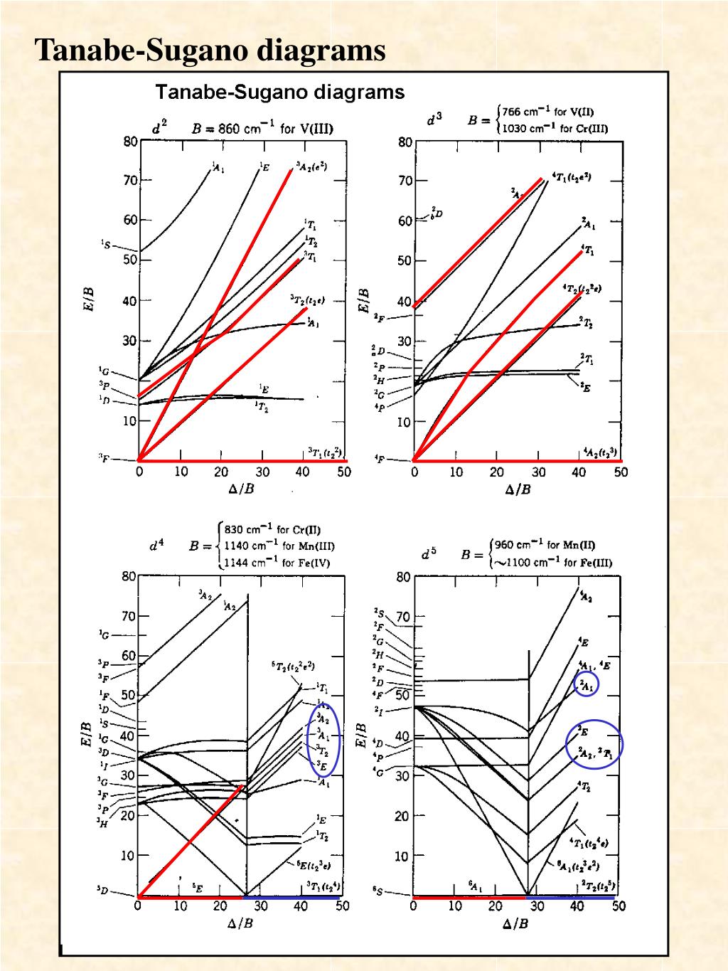
d2 Tanabe-Sugano Diagram 1A 1E 1g g 80 3A 2g 70 60 1T 1g 1T 1S 2g 3T 50 1g E/B 40 3T 2g 1A 1g 30 1G 20 1E 3P g 1D 1T 2g 10 3F 3T 0 1g ∆o/B 0 10 20 30 40 d3 Tanabe-Sugano Diagram 4T 2 1g A2g 80 70 2A 1g 4T 60 1g 50 4T 2g E/B 40 2F 2T 2g 30 2T 1g 20 2E 2G g 4P 10 4F 4A 0 2g ∆o/B 0 10 20 30 40 50 d4 Tanabe-Sugano Diagram 3A 1 2g A2
田边-菅野图(Tanabe-Sugano diagram)用于预测配合物的紫外和可见光谱。 预测结果与光谱实验结果对比,可估算配体场分裂能10Dq的大小。高自旋和低自旋配合物的谱学性质都可用田边-菅野图来预测,不同于只能预测高自旋的Orgel图。 也可用其预测致高自旋至低自旋的跃迁的配体场大小。
TanabeSugano. A python-based Eigensolver for Tanabe-Sugano- & Energy-Correlation-Diagrams based on the original three proposed studies of Yukito Tanabe and Satoru Sugano for d 2-d 8 transition metal ions:. On the Absorption Spectra of Complex Ions.

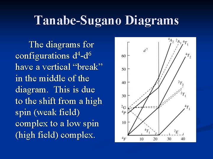
Certain Tanabe-Sugano diagrams (d 4, d 5, d 6, and d 7) also have a vertical line drawn at a specific Dq/B value, which is accompanied by a discontinuity in the slopes of the excited states' energy levels.This pucker in the lines occurs when the identity of the ground state changes, shown in the diagram below. The left depicts the relative energies of the d 7 ion states as functions of ...

T sdiagram. 1. d2 Tanabe-Sugano Diagram 1A 1E 1g g 80 3A 2g 70 60 1T 1g 1T 1S 2g 3T 50 1g E/B 40 3T 2g 1A 1g 30 1G 20 1E 3P g 1D 1T 2g 10 3F 3T 0 1g 0 10 20 30 40 ∆o/B. 2. d3 Tanabe-Sugano Diagram 4T 1g A2g 2 80 70 2A 1g 4T 60 1g 50 4T 2g E/B 40 2F 2T 2g 30 2T 1g 20 2E 2G g 4P 10 4F 4A 0 2g 0 10 20 30 40 50 ∆o/B.

The baseline in the Tanabe-Sugano diagram represents the lowest energy or ground term state. The d 2 case (not many examples documented). The electronic spectrum of the V 3+ ion, where V(III) is doped into alumina (Al 2 O 3), shows three major peaks with frequencies of: ν1=17400 cm-1, ν2=25400 cm-1 and ν3=34500 cm-1.

This is normally done through a Tanabe-Sugano diagram where energy is plotted against the magnitude of the crystal field splitting parameter for a d3 ion (Figure 2). Figure 2. Tanabe-Sugano Diagram appropriate for Cr(III). The vertical arrow denotes the relevant d-d transition for determining ∆o. After Tanabe, Y.; Sugano, S. J. Phys. Soc. Jpn. 1954, 9, 753 . Chem242. Int. Inorg. Chem. UMass ...
The Orgel and Tanabe-Sugano diagram for d8-configuration can be used to estimate the value of crystal field splitting energy for these transition metal complexes. (a) (b) Figure 39. The (a) Orgel and (b) Tanabe-Sugano diagrams for d8 complexes in the octahedral crystal field. Consider the example of [Ni(H2O)6]2+. 1.


0 Response to "43 tanabe-sugano diagram"
Post a Comment