44 two pipe steam system diagram
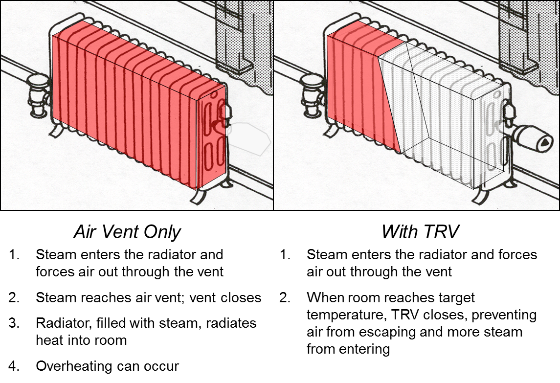
An optimized two-pipe steam system retrofitted with orifice plates, thermostatic radiator valves (TRVs), and properly sized vents provides efficient and balanced heat. air vent TRV steam water. nyc.gov/RetrofitAccelerator Tech Primer: Two-Pipe Steam Optimization AN 2019 V1 3 Transfer Pump Piping. Boiler Feed Systems. NPSH. Steam Boiler Piping. Boiler Header Connections. Piping Multiple Boilers. Boiler Water Level Controls.68 pages
steam in the system condenses. This allows all the vents and vacuum breakers to re-open and let the air back into the system. (This includes the radiators and the piping.) This one detail is critical for the system to operate properly. When the boiler fires back up for the next heating cycle, the steam will push the air out of

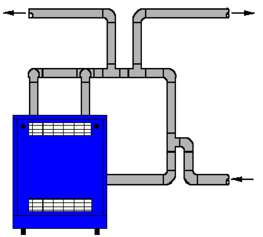
Two pipe steam system diagram
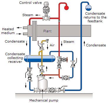
Steam Boiler Piping Diagram. Steamhead Member Posts: 14,816. September 2005. in THE MAIN WALL. the "one-pipe" or "two-pipe" parts of the system occur after the steam main leaves the boiler's header. So it wouldn't be shown on that Columbia/Utica gas steamer diagram. What type of boiler and system do you have? These pipes will carry condensate, incondensable gases, and flash steam from the trap to the condensate return system (Figure 14.2.5). Flash steam is formed as the condensate is discharged from the high-pressure space before the steam trap to the lower pressure space of the condensate return system. Steam Coil Vacuum Breaker Airflow Condensate Return Main Trap 12" Min. 2 4 Air Vent 3 5 Condensate Return Safety Drain Vacuum Breaker 6 12" Min. 1 7 7 12" Min. C-14 Recommended Piping Practices for Steam Heating Coils 1. 24" minimum if safety drain is used. 2. Safety drain is used if steam supply is modulated and the condensate system is ...
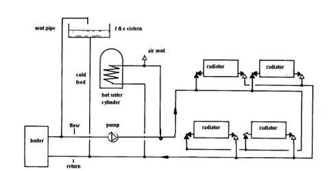
Two pipe steam system diagram. The condensate pipe is smaller than the steam pipe because it carries a liquid. In a two pipe system, the steam is kept separate from the condensate. In a one pipe system, the steam and condensate shared the same pipe. The two pipe system can be converted to a hot water system. The one pipe system cannot, without expensive re-piping. In a two ... Steam lines should ideally be arranged to fall in the direction of flow, at not less than 100 mm per 10 m of pipe (1:100).This slope will ensure that gravity (and the flow of steam), will assist in moving the condensate towards drain points so that the condensate may be safely and effectively removed (see Fig. 15.4).Any steam lines rising in the direction of flow should slope at not less than ... Installation and maintenance of the steam system are important issues, and must be considered at the design stage. Figure 3.2 Steam Distribution System As steam condenses in a process, flow is induced in the supply pipe. Condensate has a very small volume compared to the steam, and this causes a pressure drop, which causes the steam A 2-pipe HVAC system is one that uses the same piping alternately for hot water heating and chilled water cooling, as opposed to a 4-pipe system that uses separate lines for hot and chilled water. Two-pipe originated 50 or 60 years ago as a cost-effective way to add air conditioning.
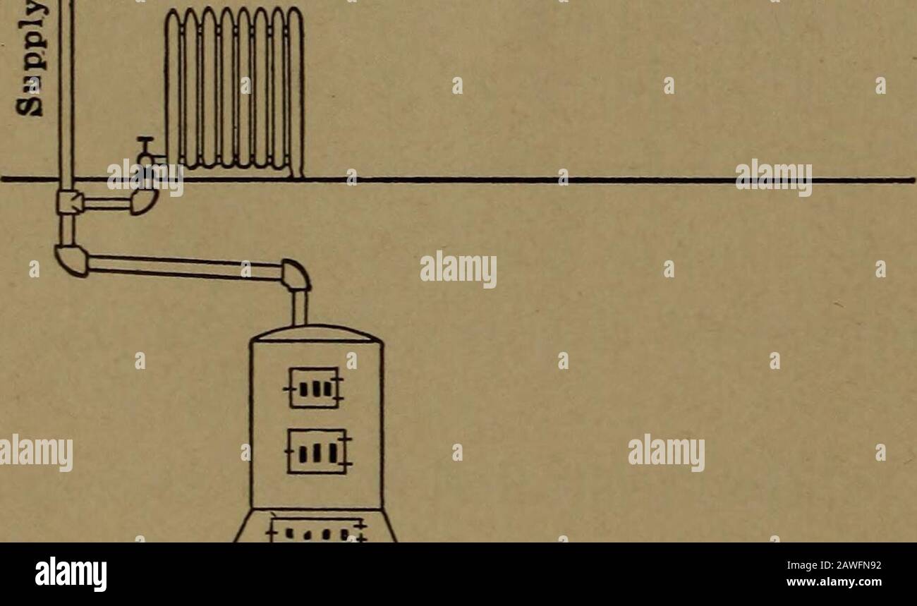
At the turn of the century there was a type of steam system called the two-pipe, air-vent system. This system had two pipes (and two supply valves) at opposite ends of the bottom of the radiator. Since this system didn't use steam traps (they hadn't invented them yet!), both pipes carried steam. It worked because of the air vents. Single Pipe Steam System with Main Pipes Pitched Towards the Boiler. Steam and condensate use the same main pipes. The condensate flows in the opposite direction of the steam. Air valves are necessary for evacuating air during start-up. The system is simple but the heat emission from radiators or in heat exchangers is hard to control. The two pipe reverse return configuration which is sometimes called 'the three pipe system' is different to the two pipe system in the way water returns to the boiler. In a two pipe system once the water has left the first radiator it returns to the boiler to be reheated, and so with the second and third etc. a) The lowest steam carrying pipe must be at least 28 inches above the normal boiler water line. B. SYSTEM CHECKLIST 1. The system piping must provide dry steam—wet steam causes water hammer, component damage and water level problems. 2. Make sure air vents are working. a) The most important vents are the main and riser vents.
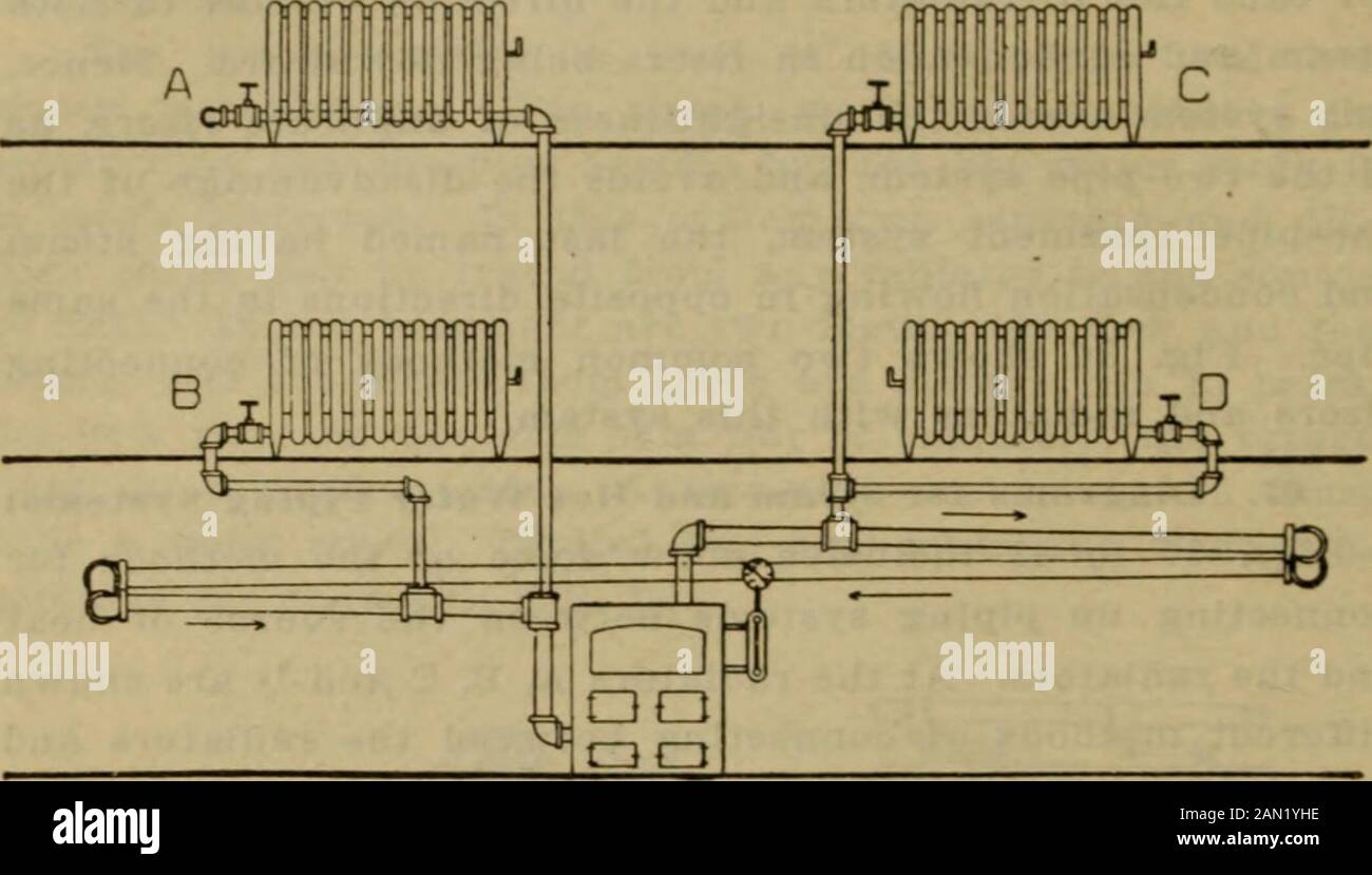
This is a steam system so there should be no water in the radiator when the boilers off. He takes the cover off and gets douched by five or six gallons of water. And of course the room will have white carpet and be on the second floor so that the water can destroy the ceiling on the first floor as it pours thru the hole the pipe uses. I've seen that same problem with start up on large single zone two pipe systems with our outdoor reset mod steam boilers with the system converted to supply valve orifices. However, we've found so far that running only 1/3 to 1/2 of the orificed radiator capacity is all that is needed to get the system moving. Fig. 5 is a diagram of a two-pipe system. Here, each radiator has a supply pipe, through which the steam enters, and a return pipe which conducts the water ... In this excerpt from his Dead Men's Steam School seminar, Dan Holohan looks at all of the different types of piping that you will find on steam heating syste...
Dec 13, 2014 — I've also attached a diagram of a typical 2 pipe steam system. Do you have steam traps on your radiators? Why I'm asking is that while most 2 pipe systems ...90 year-old house, 2-pipe steam, and all kinds of issuesNov 12, 2017Two Pipe Steam - Air Vents and some other confusionOct 19, 2013Two pipe system some cold Radiators - Heating Help: The WallDec 21, 2011Two pipe steam, no vents, no traps. - Heating Help: The WallDec 7, 2016More results from forum.heatinghelp.com
They just put in these two-pipe, air-vent systems, which look remarkably like two-pipe, direct-return hot-water systems. The steam leaves the boiler and heads up into the building. It favors the supply lines, of course, because these are usually larger than the return lines by at least one size. Steam follows the path of least resistance.
Four-Pipe HVAC System. This system configuration uses twice as much piping as a two-pipe HVAC system, and thus it is more expensive and takes longer to install. In addition, a four-pipe system requires more space to accommodate two hydronic piping circuits that run through the building. The increased number of fixtures, valves and connection ...
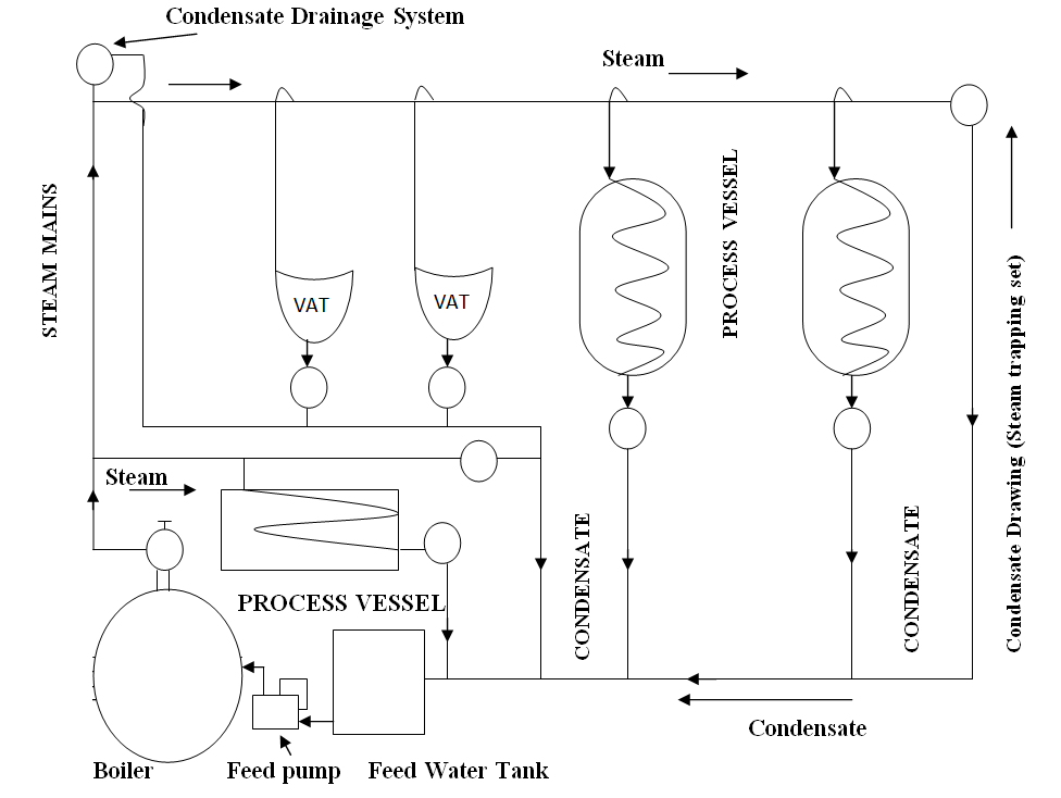
2-1 2. PROFILING THE STEAM SYSTEM 2.1 OVERVIEW AND GENERAL PRINCIPLES In general, operational changes are based on economic factors. Thus, the economics of the steam system should be determined. The main factors in this evaluation are associated with the fuel supplied to the boilers. The total cost of fuel supplied to the boilers will provide ...
When steam condenses, its volume is dramatically reduced, which results in a localised reduction in pressure. This pressure drop through the system creates the flow of steam through the pipes. The steam generated in the boiler must be conveyed through the pipework to the point where its heat energy is required.

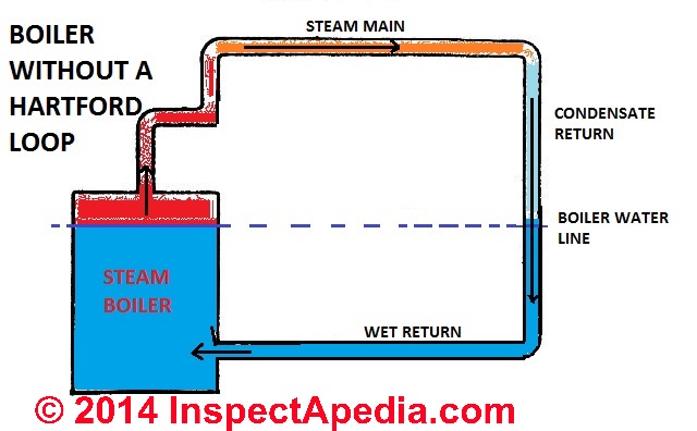
The primary component of a Hartford loop diagram is the location of a Hartford loop top and its distance from the boiler water top. Standard Hartford loop diagrams generally place the top of the loop 2 inches below the steam boiler's water line. hartford loop steam piping diagram is among the photos we discovered on the net from reputable sources.
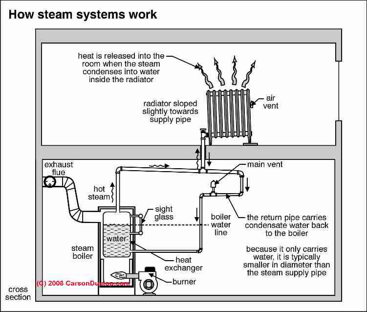
Guide to steam heat radiator piping connections: this article describes the piping connections for steam heating radiators. We explain the difference between one pipe and two pipe steam heating systems. We illustrate upfeed steam pipes, downfeed steam pipes, and we make clear how to figure out what type of steam heat is installed in a building - insofar as the steam heat distribution is concerned.
1. Piping systems designed for steam pressure below 25 psig are low-pressure steam systems. Piping systems designed for steam pressures from 25 psig up to and including 125 psig are medium-pressure steam. Systems 126 psig and above are high-pressure steam. 2. Distribution piping complying with Thermal Energy Cooperative (TECO) requirements is

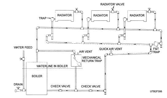
Fundamentals Of Two-Pipe Steam Radiators. In two-pipe steam installations, steam flows from the boiler to the radiators through an inlet pipe. Once the steam condenses it returns to the boiler through a second outlet pipe. You can typically recognise a two-pipe system from the two pipes and lack of steam vent attached to the radiator.
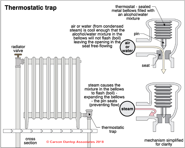
The two-pipe vapor system with an alternating return trap, as shown in figure 3-6, is an improvement over the one-pipe system. The return from the radiator has a thermostatic trap that permits the flow of condensate and air from the radiator. It also prevents steam from leaving the radiator. Because the return mains are at atmospheric pressure ...
to the system. The prevention of heat loss is a priority in both one and two pipe steam heating; the pipes should be properly insulated. When properly insulated efficiency will improve as less heat is escaping from the system meaning steam will be hotter when it reaches the radiators additionally reheating condensate will require less energy.
Read an introduction to two-pipe steam systems here. One-pipe steam radiator components. The inlet, or control, valve must have a large internal bore: minimum of 1" for radiators of 5000 BTUs or fewer; at least 1-¼" above that. On a one-pipe steam radiator it must be fully open or fully closed.
A general rule of thumb is that 1 psi of steam will raise water about 2 feet. For example, a 5 psi system should not have condensate lines higher than 10 feet above the steam trap. Properly Size Steam Trap Drip Leg Lines. Not only must steam traps be piped off the bottom of the steam lines, the pipe must be properly sized.
Steam Coil Vacuum Breaker Airflow Condensate Return Main Trap 12" Min. 2 4 Air Vent 3 5 Condensate Return Safety Drain Vacuum Breaker 6 12" Min. 1 7 7 12" Min. C-14 Recommended Piping Practices for Steam Heating Coils 1. 24" minimum if safety drain is used. 2. Safety drain is used if steam supply is modulated and the condensate system is ...

These pipes will carry condensate, incondensable gases, and flash steam from the trap to the condensate return system (Figure 14.2.5). Flash steam is formed as the condensate is discharged from the high-pressure space before the steam trap to the lower pressure space of the condensate return system.

Steam Boiler Piping Diagram. Steamhead Member Posts: 14,816. September 2005. in THE MAIN WALL. the "one-pipe" or "two-pipe" parts of the system occur after the steam main leaves the boiler's header. So it wouldn't be shown on that Columbia/Utica gas steamer diagram. What type of boiler and system do you have?


0 Response to "44 two pipe steam system diagram"
Post a Comment