41 Moment Diagram For Beam
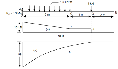
PDF Shear Forces and Bending Moments in Beams PDF_C8_b (Shear Forces and Bending Moments in Beams) Q6: A simply supported beam with a triangularly distributed downward load is shown in Fig. Calculate reaction; draw shear force diagram; find location of V=0; calculate maximum moment, and draw the moment diagram. 6k/ft 9 ft RA = (27k)(9-6)/9= 9k A B F = (0.5x6x9) = 27k x = (2/3)(9) = 6 ft Beam Calculator Online (Calculate the reactions, Draws ... Setting the bending diagrams of beam. Calculate the reactions at the supports of a beam. Bending moment diagram (BMD) Shear force diagram (SFD) Axial force diagram. Invert Diagram of Moment (BMD) - Moment is positive, when tension at the bottom of the beam.
PDF Diagram Generator for Single and Multi-Span Beams to automate the generation of shear, moment, and deflection diagrams for various beams. 2.1 Euler-Bernoulli Beam Theory Euler-Bernoulli Beam Theory is the most basic beam theory that there is, relating deflection to the applied load in the classic fourth order differential Equation [1]: d2 dz-w d (EI dx2)= q(x) (1)

Moment diagram for beam
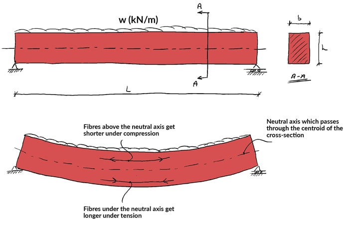
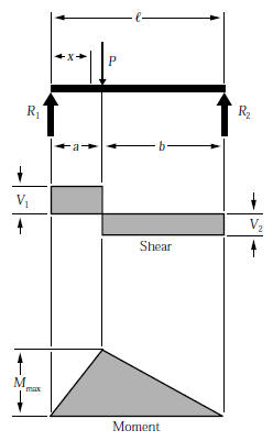
Shear and Moment Diagrams | Strength of Materials Review ... Shear and Moment Diagrams Shear and Moment Diagrams Consider a simple beam shown of length L that carries a uniform load of w (N/m) throughout its length and is held in equilibrium by reactions R 1 and R 2. Assume that the beam is cut at point C a distance of x from he left support and the portion of the beam to the right of C be removed. Mechanics Map - Shear and Moment Diagrams The moment diagram will plot out the internal bending moment within a horizontal beam that is subjected to multiple forces and moments perpendicular to the length of the beam. PDF Shear and Moment Diagrams - Memphis procedure for constructing the shear and moment diagrams for a beam. 3. To construct the moment diagram, first, establish the M and x axes and plot the value of the moment at each end of the beam. Shear and Moment Diagrams Procedure for analysis-the following is a procedure for constructing the shear and moment diagrams for a beam.
Moment diagram for beam. Reinforced Concrete Beam Calculator - Bending Moment Diagram 27.05.2015 · The Reinforcement Beam Section Calculator is a failry simple tool, and is small part of our fully featured Reinforced Concrete Beam Design software offered by SkyCiv. This software will display the full report and worked example of reinforced concrete design calculations as per ACI, AS and Eurocode design standards. These results include moment capacity checks, … Draw the shear and moment diagram for the given beam ... Civil Engineering questions and answers. Draw the shear and moment diagram for the given beam. Clearly label all points on the diagrams. For partial credit give the reactions. Use lb and ft for units. 10 lb/ft 180 lb 40 ft 15 ft 20 ft 20 ft. Question: Draw the shear and moment diagram for the given beam. Clearly label all points on the diagrams. Shear and moment diagram - Wikipedia Shear and Bending moment diagram for a simply supported beam with a concentrated load at mid-span. Shear and bending moment diagrams are analytical tools used in conjunction with structural analysis to help perform structural design by determining the value of shear force and bending moment at a given point of a structural element such as a beam . PDF 4. Bending Moment and Shear Force Diagram Construction of bending moment diagram xThe bending moment diagram is obtained by proceeding continuously along the length of beam from the left hand end and summing up the areas of shear force diagrams using proper sign convention.
PDF Lecture 2 - Shear and Bending Moment and Review of Stress 3.2 - Shear Force & Bending Moment Diagrams What if we sectioned the beam and exposed internal forces and moments. This exposes the internal Normal Force Shear Force Bending Moment ! What if we performed many section at ifferent values Of x, we will be able to plot the internal forces and bending moments, N(x), V(x), M(x) as a function Of position! Bending Moment Diagram - BrainDuniya DRAWING OF BEAM DIAGRAMS. In drawing of bending moment diagram, we have to follow certain guidelines in strict manner as explained in earlier article guide lines of beam diagram. For illustration and clear understanding of the process of drawing of beam diagrams, we have drawn following typical beam diagrams with very common beams and their loading patterns. Beam Stress & Deflection | MechaniCalc A shear diagram shows the shear force along the length of the beam, and a moment diagram shows the bending moment along the length of the beam. These diagrams are typically shown stacked on top of one another, and the combination of these two diagrams is a shear-moment diagram. PDF Module -4 Shear Force and Bending Moment Diagrams a beam. The moment diagram can also be used to predict the qualitative shape of the deflected axis of a beam. General Guidelines on Construction of SFD and BMD Before we go on to solving problems, several standard procedures (or practices) in relation with construction of shear force and bending moment diagrams need to be noted.
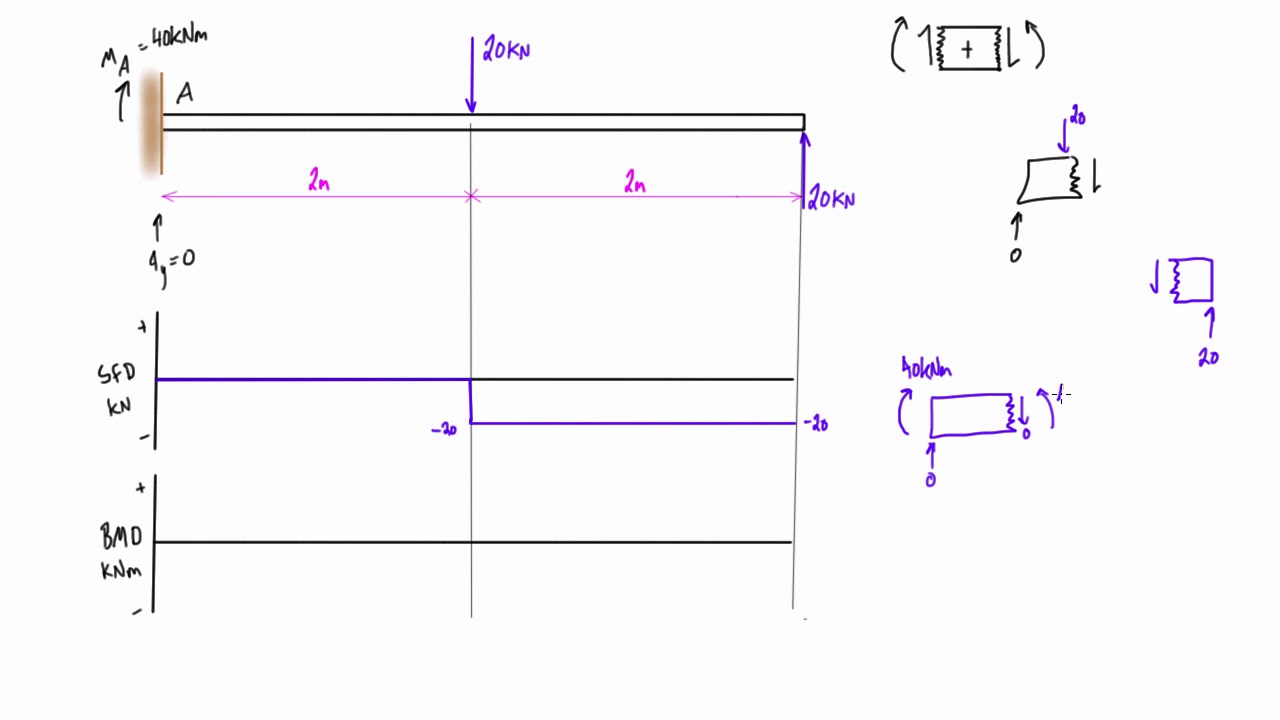
Bending moment and shear force diagram of a cantilever beam 11.09.2017 · In this article Learn :cantilever beam Bending moment diagram B.M.D. and shear force diagram S.F.D. of a cantilever beam having point load at the end,several point loads,U.D.L. Over Whole Span ,U.D.L. not over the whole span,U.D.L. from support to some distance,U.D.L. Somewhere on the beam,Combination of Point Loads and U.D.L. 6.2 Shear/Moment Diagrams - Engineering Mechanics: Statics Moment Diagram The moment diagram will plot out the internal bending moment within a horizontal beam that is subjected to multiple forces and moments perpendicular to the length of the beam. PDF BEAM DIAGRAMS AND FORMULAS - Arch Exam Academy beam diagrams and formulas by waterman 55 1. simple beam-uniformly distributed load 2. simple beam-load increasing uniformly to one end. 3. simple beam-load increasing uniformly to center 4. simple beam-uniformly load partially distributed. 5. simple beam-uniform load partially distributed at one end PDF Chapter 4 Shear and Moment In Beams - ncyu.edu.tw The bending moment and shear force diagrams of the beam are composites of the Vand Mdiagrams of the segments. These diagrams are usually discontinuous, or have discontinuous slopes. At the end-points of the segments due to discontinuities in loading. Sample Problem4.1 The simply supported beam in Fig. (a) carries two concentrated loads.
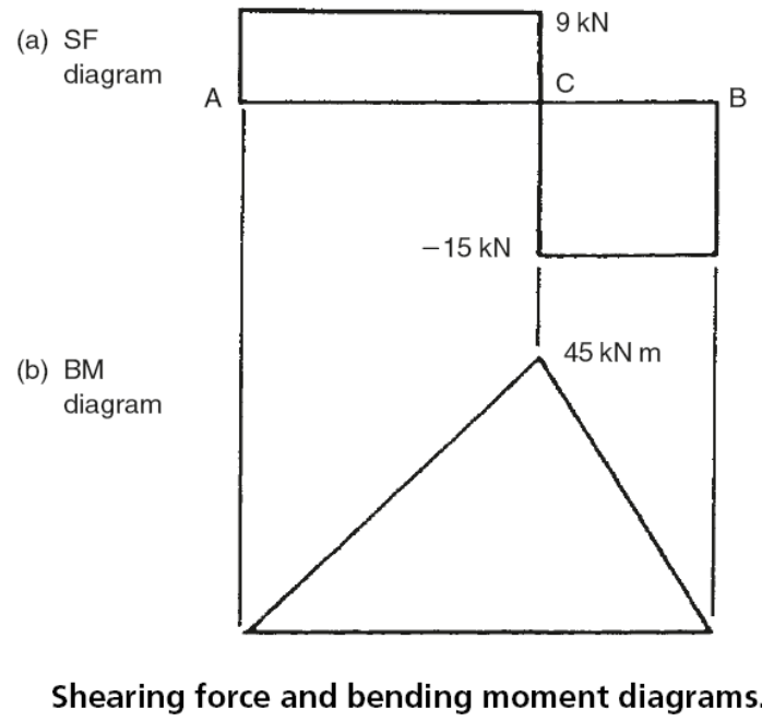
Shear force and bending moment diagram for beams with fc ...
Trapezoidal Distributed Load Moment Diagram 23.09.2018 · BEAM FORMULAS WITH SHEAR AND MOMENT DIAGRAMS Beam Fixed at One End, Supported at Other – Uniformly Distributed Load. Beam Fixed at One. Hi all, I'm experiencing a difficulty understanding how the trapezoidal loads are distributed and how to shear moment diagrams are drawn for. Problem Under cruising conditions the distributed load …
Bending moment diagrams for a simply supported beam subjected ...
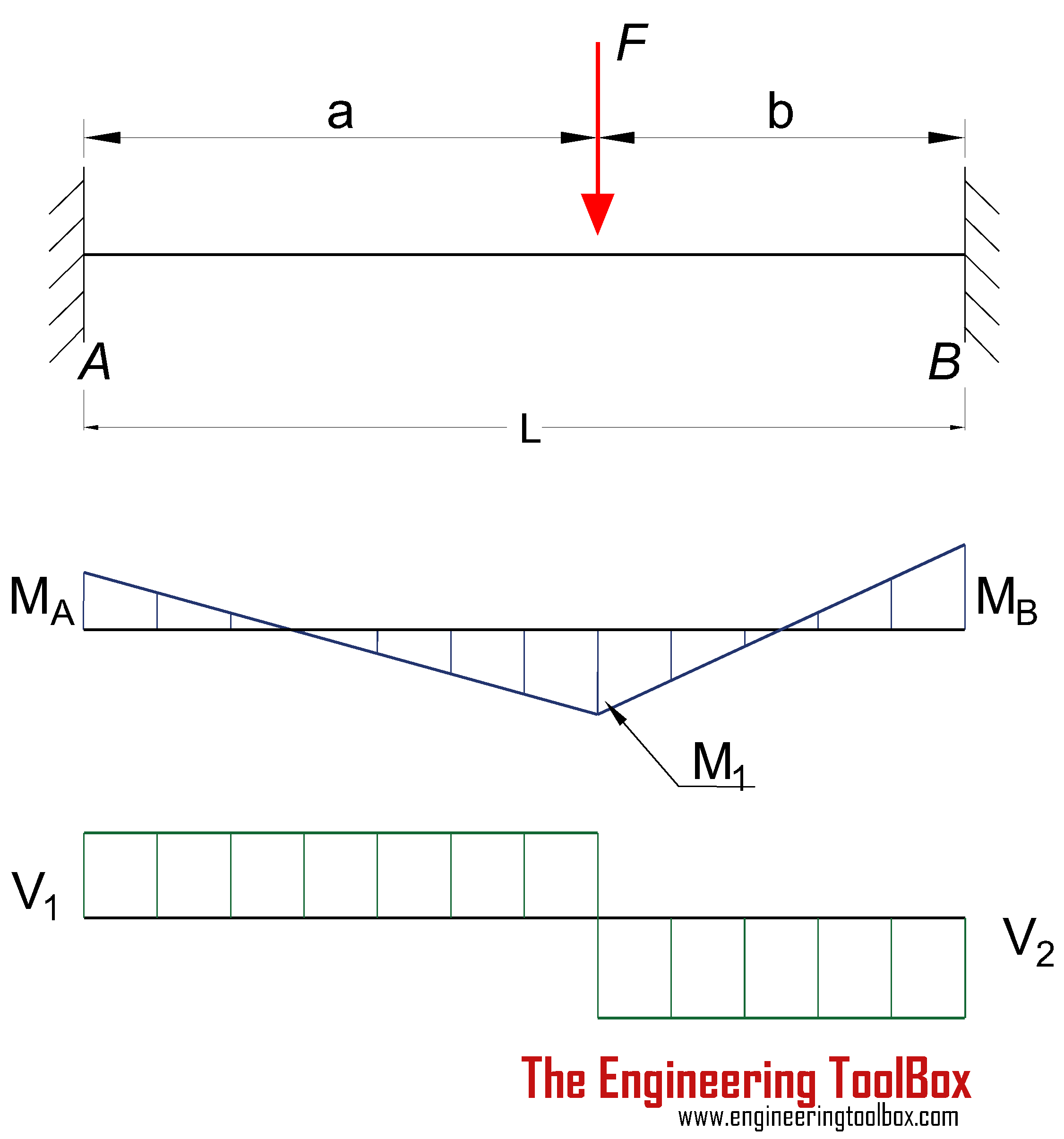
PDF Beam Diagrams and Formulas BEAM DIAGRAMS AND FORMULAS Table 3-23 (continued) Shears, Moments and Deflections 13. BEAM FIXED AT ONE END, SUPPORTED AT OTHER-CONCENTRATED LOAD AT CENTER

Bending Moment Diagram - an overview | ScienceDirect Topics
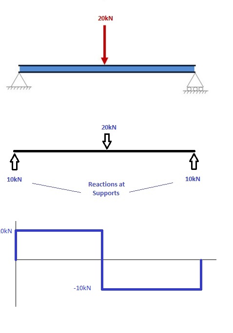
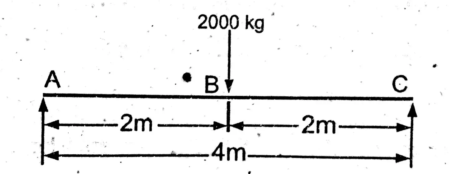
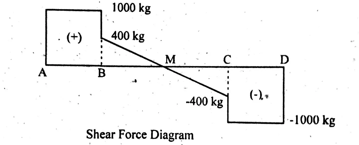
Shear Force & Bending Moment Diagram of Simply Supported Beam 16.10.2014 · Bending Moment Diagram Simply Support Beam with UDL & Point Load Example. Draw shear force and bending moment diagram of simply supported beam carrying uniform distributed load and point loads. As shown in figure. Solution. First find reactions R1 and R2 of simply supported beam. Reactions will be equal. Since, beam is symmetrical.
Determining the Shear Force and Bending Moment Equations of ...
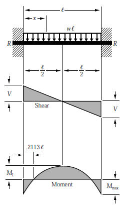
PDF Reactions, Shear Force and Moment Diagrams Dr. M.E. Haque, P.E. Beam Reactions, Shear and Moment (Page 7 of 12) w L Sym. 2 / 8 - w x2 /2 w x2 /2 P 1 L / 4 P 2 x w L / 2 + P 1 / 2 MOMENT DIAGRAMS Fig. 1 Fig. 2 Fig. 3 Algebraic summation of coordinates of these three moment diagrams will produce the final moment diagram.

Draw the shear force and bending moment diagrams for the beam ...
PDF Design Aid 6 Beam Design Formulas with Shear and Moment ... and moment diagrams with accompanying formulas for design of beams under various static loading conditions. Shear and moment diagrams and formulas are excerpted from the Western Woods Use Book, 4th edition, and are provided herein as a courtesy of Western Wood Products Association. Introduction Notations Relative to "Shear and Moment Diagrams"

Cantilever beam Shear Force and Bending Moment diagram with Triangular load
PDF Shear and Moment Equations and Diagrams for Beams 2 Shear and Bending Moment Diagrams 1.Determine all the reactions on the beam. 2.Draw the entire beam showing all loads and reactions. 3.Using V0(x) = −w(x) sketch V(x) for the whole beam. According the sign convention on the previous page: (a)Upward acting forces give rise to positive changes in V(x).
4.3 Determinate Beam Analysis | Learn About Structures
Moment area method for beam deflections : article ... It illustrates a simple beam, deflected by some random loading, and the corresponding bending moment diagram. Theorem 1 The change of slope between any two points of the elastic curve is equal to the area of the bending moment diagram, between these two points, divided by . Slopes are measured in radians for the needs of the moment area method.
Beam Reactions and Diagrams – Strength of Materials ...
Draw the shear and moment diagrams for the cantilevered beam The shear and bending moment functions can be plotted on a graph paper, taking the beam as a reference, called shear force and bending moment diagrams. These diagrams help engineers to decide where to reinforce the beam and were to provide greater areas of the cross section to the beam to withstand the loading. Fundamentals

Drawing Bending Moment Diagrams Effectively - MechanicalBase
Free Beam Calculator - Optimal Beam Free Beam Calculator for Statically Indeterminate Beams. Support Reactions. Shear Diagram. Moment Diagram. Indeterminate / Continuous Beams. Premium: Deflection and Stress Diagrams. Premium: Custom and Standard Sections or Materials. Premium: Save Unlimited Models and Sections. Premium: PDF Reports and Custom Logo.

1. Draw a shear force and bending moment diagram for the beam ...
Shear Force and Bending Moment Diagram for simply ... 01.12.2015 · Shear Force and Bending Moment Diagram for simply supported beam version 1.0.0.0 (3.44 KB) by Sajeer Modavan This Matlab code can be used for finding Support reaction, Maximum Bending Moment, SFD and BMD
How to Calculate Bending Moment Diagram? | SkyCiv
The Ultimate Guide to Shear and Moment Diagrams ... 💡 The internal bending moment , is the bending moment we represent in a bending moment diagram. The bending moment diagram shows how (and therefore normal stress) varies across a structure. If we know the state of longitudinal or normal stress due to bending at a given section in a structure we can work out the corresponding bending moment.

Cantilever beam response: support reactions, beam moment ...
Bending Moment and Shear Force Diagram Calculator | The ... There are also examples and random beam generators which will allow you to experiment on how different loads affect beam analysis and the shear force and bending moment of a beam. Bending Moment Diagram is powered by the team at SkyCiv Engineering - who offer Student and Professional packages that give users access to a variety of Structural Engineering …

Drawing Bending Moment Diagrams Effectively - MechanicalBase
Free Online Beam Calculator | SkyCiv Engineering Free online beam calculator for generating the reactions, calculating the deflection of a steel or wood beam, drawing the shear and moment diagrams for the beam. This is the free version of our full SkyCiv Beam Software. This can be accessed under any of our Paid Accounts, which also includes a full structural analysis software.

a) Displacement response, (b) Bending moment diagram and (c ...
Shear Force and bending moment diagram - ExtruDesign 04.09.2017 · Shear force and Bending moment Diagram for a Cantilever beam with a Point load at the free end. Shear force and Bending moment Diagram for a Cantilever beam with a Uniformly distributed load. SFD and BMD for a Cantilever beam with a Uniformly varying load. Reference: Textbook of Strength of Materials by Rk Bansal. Filed Under: Machine Design, …

SHEAR FORCE AND BENDING MOMENT DIAGRAM FOR CANTILEVER BEAM ...
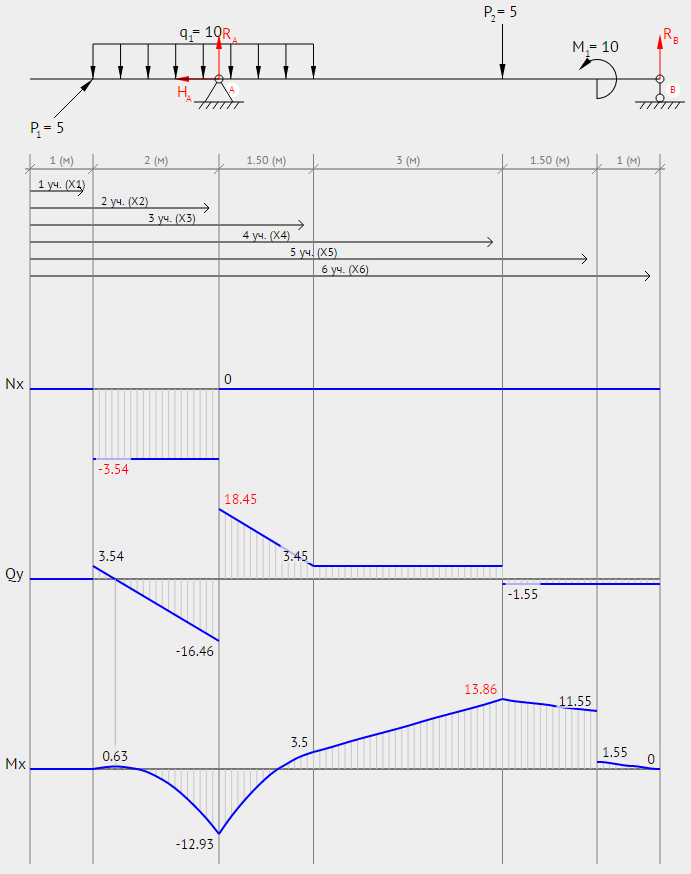
BEAMGURU.COM - Beam Calculator and Frame/Truss Beam ... BEAM GURU .COM is a online calculator that generates Bending Moment Diagrams (BMD) and Shear Force Diagrams (SFD), Axial Force Diagrams (AFD) for any statically determinate (most simply supported and cantilever beams) and statically indeterminate beams, frames and trusses.
Can you draw the shear force and bending moment diagrams of ...
How to Calculate Bending Moment Diagram? | SkyCiv 11.11.2021 · Free Beam Calculator. Calculating Bending Moment Diagram by Hand 1. Calculate reactions at supports and draw Free Body Diagram (FBD) If you’re not sure how to determine the reactions at the supports – please see this tutorial first. Once you have the reactions, draw your Free Body Diagram and Shear Force Diagram underneath the beam. Finally ...
The Ultimate Guide to Shear and Moment Diagrams ...
Triangular Distributed Load Shear And Moment Diagram 16.01.2019 · Jan 28, · Step 2: Construct the shear force diagram for the beam with these reactions. Step 3: Using the shear force diagram, construct the bending moment diagram. You are trying to construct the moment diagram by jumping in the middle of the process without completing the basic steps (1 . It's because the shear diagram is triangular under a uniformly …

Bending Moment Diagram - an overview | ScienceDirect Topics
PDF Shear and Moment Diagrams - Memphis procedure for constructing the shear and moment diagrams for a beam. 3. To construct the moment diagram, first, establish the M and x axes and plot the value of the moment at each end of the beam. Shear and Moment Diagrams Procedure for analysis-the following is a procedure for constructing the shear and moment diagrams for a beam.

Shear and Moment Diagram for Beam - Mo Civil Engineering
Mechanics Map - Shear and Moment Diagrams The moment diagram will plot out the internal bending moment within a horizontal beam that is subjected to multiple forces and moments perpendicular to the length of the beam.
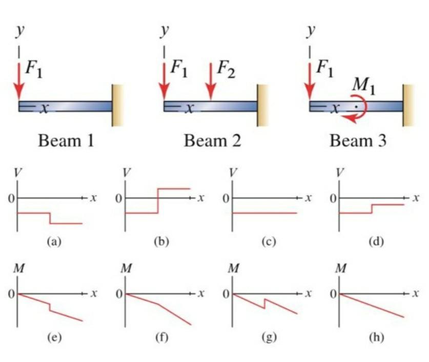
Solved Which of the following is the moment diagram of: Beam ...
Shear and Moment Diagrams | Strength of Materials Review ... Shear and Moment Diagrams Shear and Moment Diagrams Consider a simple beam shown of length L that carries a uniform load of w (N/m) throughout its length and is held in equilibrium by reactions R 1 and R 2. Assume that the beam is cut at point C a distance of x from he left support and the portion of the beam to the right of C be removed.
BEAM FORMULAS WITH SHEAR AND MOM

Shear force and bending moment diagram - MechanicalStuff4u
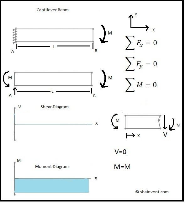
Shear and Moment Diagrams - S.B.A. Invent
How to Draw Shear Force & Bending Moment Diagram | Simply ...
Beams - Fixed at Both Ends - Continuous and Point Loads
Shear force and bending moment diagram practice problem #6

Shear force and bending moment diagram practice problem #1
How to Draw Shear Force & Bending Moment Diagram | Simply ...
Calculations for Shear Force and Bending Moment diagram for ...

Drawing Shear and Moment Diagrams for Beam - YouTube
Draw the shear force diagram of beam, Mechanical Engineering
BEAM FORMULAS WITH SHEAR AND MOM

Shear and Moment Diagram for Beam with Hinge - Mechanics of Materials
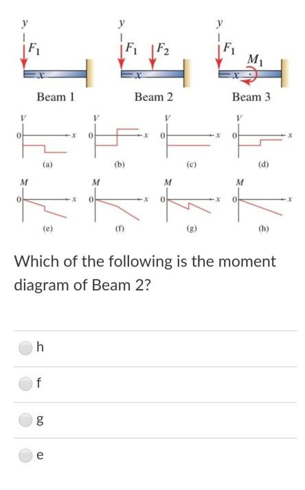
Solved Which of the following is the moment diagram of beam ...

Pin on PDD project development and documentation
Beam Analysis - Beam with uniformly distributed load(UDL ...
Chapter 4: Internal Forces in Beams and Frames” in ...

Part A Draw the shear diagram for the beam. Part B Draw the ...
6.2 Shear/Moment Diagrams – Engineering Mechanics: Statics

BEAM FORMULAS WITH SHEAR AND MOM
Shear Force And Bending diagrams - Roy Mech
0 Response to "41 Moment Diagram For Beam"
Post a Comment