43 livewell timer module wiring diagram
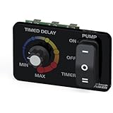
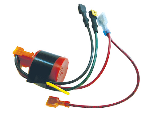
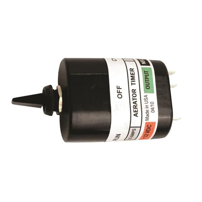
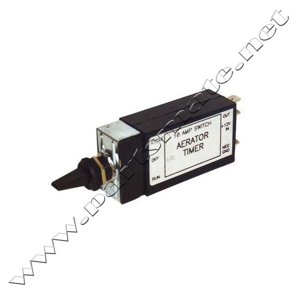
88823 Livewell Timer Wiring Diagram Wiring Resources 911 1000 E 1500 Livewell 24v 358 101 00 Shurflo Wiring Diagram 1997 202 G3 Live Well Switch Wiring Wiring Diagram Rule Tournament Series Livewell Wiring Diagram for livewell pumps and bilge pump. Depends on how it is rigged up. 12V, 10A, 3 wires, easy installation. Simple wiring diagram included. Can run 2 pumps. Pump turns on at the end of selected delay period. Wiring requires a good Ground. The reports above show ratings of the best overal, best cheap Livewell Aerator Timer Module...
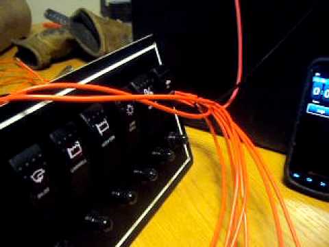
LIVEWELL CONTROL CENTER TIMER Part # 6002 HOOK UP DIAGRAM. RED BLACK. After mounting panel, string wire to battery and pump areas. The RED wire connects to the Battery (+) positive, the BLACK wire connects to the Pump (-) negative, the BROWN/WHITE wire connects to...

Livewell timer module wiring diagram
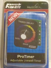
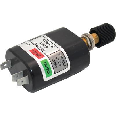
This is our user Adjustable Livewell Timer: MADE TO USE IN ANY BOAT: This Automatic Livewell Timer switch and Livewell Timer Module turns the livewell baitwell pump in your boat on and off. How are we different? Patented Technology having 3 adjustable time settings. Livewell Aerator Switch Livewell Aerator Timer Module Timer Aerator for Boat Live Well Timer Wiring Diagram LiveWell Aerator Pump Marine Livewell Timers Johnson Livewell Pump... This page is dedicated to Wiring Diagrams that can hopefully get you through a difficult wiring task or just to learn some basics in how to wire a 2-way switch, 3-way If you don't see a wiring diagram you are looking for on this page, then check out my Sitemap page for more information you may find helpful.
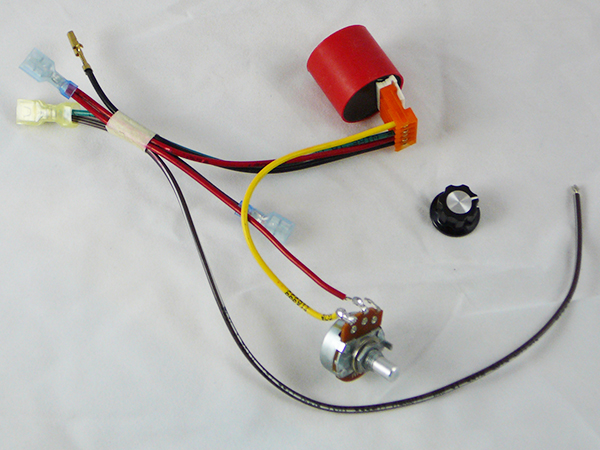
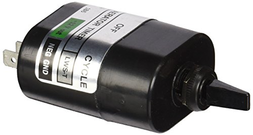
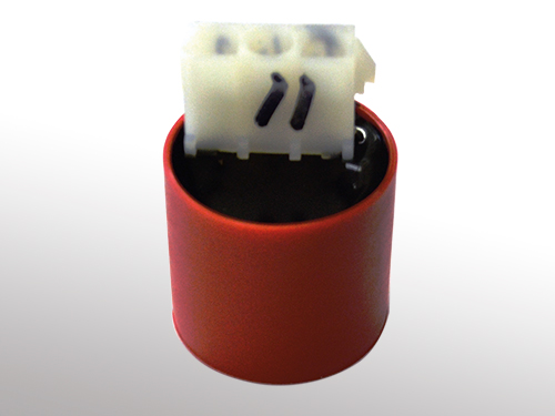
Livewell timer module wiring diagram. Discover best Timer Wiring Diagram images and ideas on Bing. Updated daily with the schematron.org Livewell Aerator Timer Solid-state cycle module switches pump to on, or to a run time of 30 seconds on/. An easy-to-follow wiring diagram and easy-set design makes this a perfect... Livewell Timer Module. Model: Brand: POLY PLANAR. Easy to mount Small package size IP68 rated High current capacity Timing cycle can be customized Rugged construction Sealed automotive connector Harness available. Leisure Lectronics Variable Livewell Timer Aerator Pump 12V Switch for Boat 99. I purchased this item to allow for a timed running of my aerator pump. It was very easy to install as the manufacturer included a wiring diagram. Livewell Timer Wiring Diagram. Take your livewell to the next level. Place the knob onto the stem with the white indicator pointing to MIN. Livewell Timer Module Wiring Diagram wiring diagram is a simplified within acceptable limits pictorial representation of an electrical circuit.
Livewell Timer Wiring Diagram Wiring Diagram. Rule Livewell Pump Parts Pumps Australia Installation Wiring. Details About 12v 600gph Cartridge Aerator Pump Livewell Live Bait Tank Boat Bilge Pump Sale. Basic Electrical Home Wiring Diagrams & Tutorials UPS / Inverter Wiring Diagrams & Connection Solar Panel Wiring & Installation Diagrams Batteries Wiring Connections and Diagrams Single Phase & Three Phase Wiring Diagrams (1-Phase & 3-Phase Wiring)Three Phase Motor Power & Control... Livewell Timer Wiring Diagram Source: wiki.diyfaq.org.uk. Read wiring diagrams from negative to positive plus redraw the routine as a straight collection. All circuits usually are the same ~ voltage, ground, individual component, and changes. Boat Livewell Timer Installation. Nitrous System Wiring Diagrams Dragstuff. Admiral Washer Wiring Diagram Wiring Diagram. Digi Set Nitrous Wiring Diagram. Off Delay Timer Wiring Diagram Online Wiring Diagram. Simple Light Switch Wiring Basic Electronics Wiring Diagram.
Live Well Timer Wiring Diagram For Switch. Line diagram of a one way lighting circuit using in Line diagram of a one way lighting circuit using in line method fig 1. Wiring Diagram for livewell pumps and bilge pump. The other switch will need. The time of the timer works perfect on my leaky live well. Livewell Timer Wiring Diagram. Nov 25 2021. You have remained in right site to start getting this info. acquire the livewell timer wiring diagram partner that we have the funds for here and check out the link. LiveWell aerator timer operates the pump in cycling On-Off mode. The period duration can be set from 1 sec to 16 hours. The pump can be configured to To adjust timer's configurations put the module into the configuration mode by applying power and then connecting the White wire to the ground. labeled "2". livewell button "1" is for the main well and "2" for the bait well. When the main 30A breaker is closed, the power module and the keypad are powered. Pressing the livewell timer once starts the low aeration cycle of one minute on and two minutes off.

AUTOMATIC Cycling 12V Livewell Aerator Timer Switch fish ...
Read cabling diagrams from bad to positive and redraw the signal as a straight collection. All circuits are the same - voltage, ground, single component, and switches. Livewell Timer Module Wiring Diagram Source: i.ebayimg.com.

NEW RANGER LOWE TRITON BOAT 4 WIRE FISHING BOAT AERATOR ...
› Get more: Education. Livewell Timer Module Wiring Diagram | autocardesign. › Top Education From www.autocardesign.org. 1 week ago Jan 02, 2020 · Livewell Timer Module Wiring Diagram - wiring diagram is a simplified within acceptable limits pictorial representation of an electrical circuit.
Timer Pod with Potentiometer
stage pin wiring diagram wiring diagram 04 cadillac power seat wiring diagram schema diagram database. A set of wiring diagrams may be required rule pumps wiring diagram cciwinterschool org rig rite manufacturing 510 marine variable livewell timer 2day delivery geri frm01 12v multifunction...

Livewell Timer: Boat Parts | eBay
Timer And Contactor R Relay Diagram - Staircase Timer Wiring Diagram - Using On Delay Timer And. Check carefully if the trigger and load circuits have been connected correctly. Livewell Timer Module Wiring Diagram Livewell Timer Module Wiring Diagram Awesome Staircase Timer Wiring.
Amazon.com: Rig Rite 520 OEM Timer Module: Automotive
Wiring Info Wiring Diagram This Livewell FillAerate rocker switch has 4 terminals on the back. That would explain the. Https Encrypted Tbn0 LIVEWELL TIMER INSTALLATION INSTRUCTIONS INSTALLATION TOOLS PUMPS LEAVE THE PLASTIC CONNECTOR COVER IN PLACE black...

ATTWOOD 142923 - Attwood Livewell Aerator Switch 142923 ...
Boat Livewell Timer Installation The wiring diagram opens in a pop-up modal box. If the pop-up blocker is turned on in your device, you are not able to download or read online the wiring diagram. Boat Livewell Timer Installation Wiring diagrams show the connections to the controller, while line...

Best Garden Hose Timer - 2020 Reviews
Read Or Download Well Timer Wiring Diagram For FREE Wiring Diagram at... Boat Livewell Timer Installation Intermatic 240v Timer Wiring Diagram

12 volt timer switch | Timers.Shop
Livewell Timer Module Wiring Diagram wiring diagram is a simplified within acceptable limits pictorial representation of an electrical circuitIt shows Using wiring diagram above attach wiring to your boats electrical system. 12V input terminal 2 12V output switch up terminal 3 to float switch 12V...
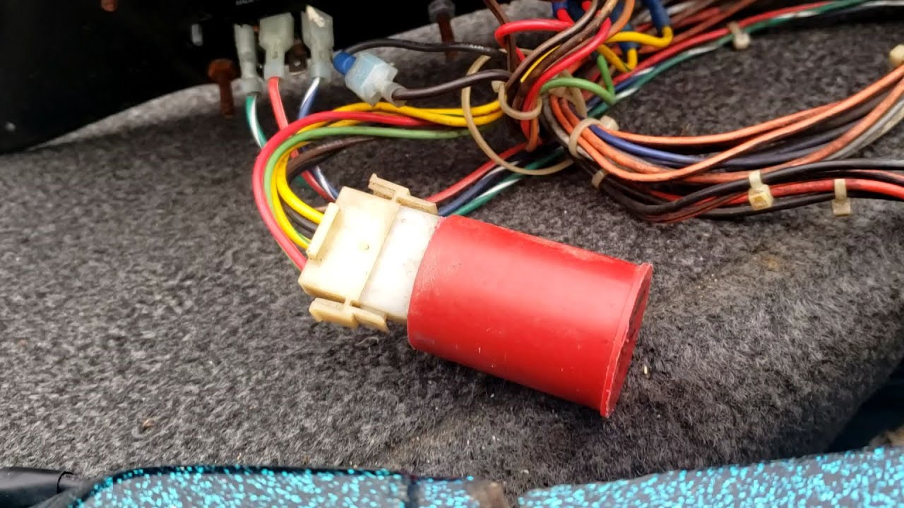
Boat livewell timer repair. Livewell pump - YouTube
88823 Livewell Timer Wiring Diagram Wiring Resources 911 1000 E 1500 Livewell 24v 358 101 00 Shurflo Wiring Diagram 1997 202 G3 Live Well Switch Wiring Wiring Diagram Rule Tournament Series Livewell Pumps 500. Using wiring diagram above attach wiring to your boats electrical system.
31 How A Livewell Works Diagram - Wiring Diagram List
timer for livewell pump. Join our Engineering Community! Agreed, 555 timer IC is the way to go, it can easily be set up with some driving circuitry such that it powers the pump On a first project it's also easy to confuse pin #s because you're wiring from the botom and they're numbered from a top view.

Livewell Timer: Boat Parts | eBay
This page is dedicated to Wiring Diagrams that can hopefully get you through a difficult wiring task or just to learn some basics in how to wire a 2-way switch, 3-way If you don't see a wiring diagram you are looking for on this page, then check out my Sitemap page for more information you may find helpful.

I am trying to install a GE SunSmart Digital Timer (3-way ...
Livewell Aerator Switch Livewell Aerator Timer Module Timer Aerator for Boat Live Well Timer Wiring Diagram LiveWell Aerator Pump Marine Livewell Timers Johnson Livewell Pump...
livewell timer | eBay
This is our user Adjustable Livewell Timer: MADE TO USE IN ANY BOAT: This Automatic Livewell Timer switch and Livewell Timer Module turns the livewell baitwell pump in your boat on and off. How are we different? Patented Technology having 3 adjustable time settings.
livewell timer not working?
http://www.rigritemfg.com/products/520_dia.gif

Compare price to livewell timer | TragerLaw.biz

Big Foot Minuteman 3 Bait and Livewell Aerator Timer | Academy

Live Well For Boat Wiring Diagram - Wiring Diagram

HW0516 Timer module (met afbeeldingen) | Afbeeldingen

12V delay timer switch

Aerator Kits / Parts - Livewell Aerator Timer Module ...

Amazon.com: Rig Rite 520 OEM Timer Module: Automotive

Well Wiring Diagram : Boat Livewell Timer Installation ...

Boat Accessories for sale.

AUTOMATIC 12V LIVEWELL Aerator Pump Timer by Leisure ...

Stratos 268 Wiring Diagram - Wiring Diagram

Schematic Timer Switch Diagram Wiring - Apartment Home Decor
Rig Rite 520 OEM Livewell Timer Module - 587963, Livewells ...
Compare price to livewell timer | TragerLaw.biz
Boat Livewell Timer Installation

Live Bait Tank | AKFF Wiki | FANDOM powered by Wikia
Livewell Switches and Panels : , Reliable Source of Nissan ...
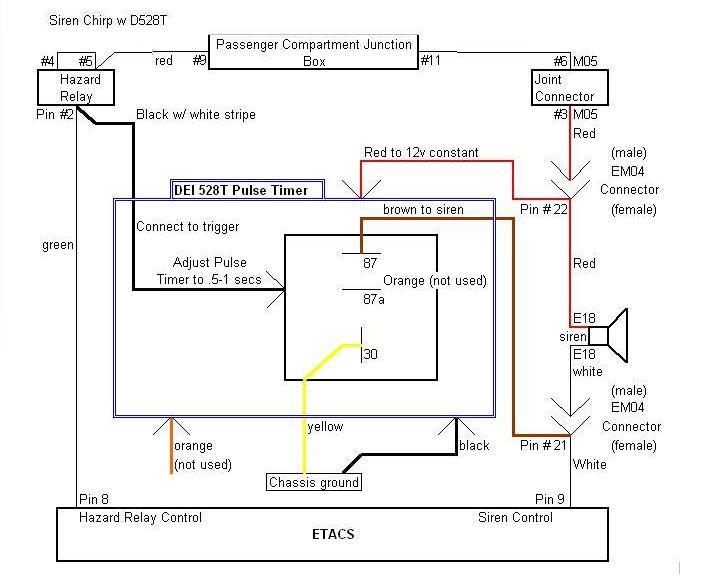
Hyundai Santa Fe Alarm Chirp Modification
Livewell Timer? Page: 2 - iboats Boating Forums | 542364
Attwood 14292-3 Livewell Aerator Switch | Walmart Canada

Steps To Success - Jersey LiveWell
Livewell Switches and Panels : , Reliable Source of Nissan ...
Electrical and Rigging Accessories | RigRite Manufacturing
![[DIAGRAM] Live Well Timer Wiring Diagram EPUB Download ...](https://cdn2.hubspot.net/hubfs/1817712/Live%20Well%20Diagram.png)
[DIAGRAM] Live Well Timer Wiring Diagram EPUB Download ...

Livewell Timer: Boat Parts | eBay

Boat Livewell Timer Installation

Livewell Timers | Jerrys Boating Supplies OnLine Store

Livewell Timer: Boat Parts | eBay
0 Response to "43 livewell timer module wiring diagram"
Post a Comment